P24 RES | RR F | R | SI | S2 | S3 S4 RCH P24 LOW LOW |
ST FM | AM CC | CC | RX | PP | IV FP FLC FLB FLA |
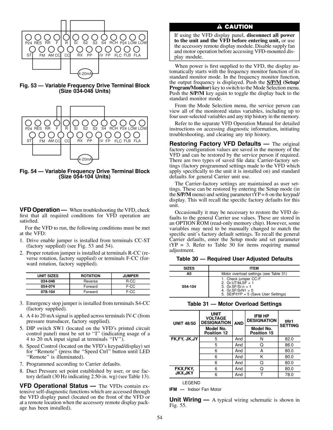
Fig. 53 Ð Variable Frequency Drive Terminal Block
(Size 034-048 Units)
P24 RES | RR F | R | SI | S2 | S3 S4 RCH P24 LOW LOW |
ST FM | AM CC | CC | RX | PP | IV FP FLC FLB FLA |
Fig. 54 Ð Variable Frequency Drive Terminal Block
(Size 054-104 Units)
VFD Operation Ð When troubleshooting the VFD, check ®rst that all required conditions for VFD operation are satis®ed.
For the VFD to run, the following conditions must be met at the VFD:
1. | Drive enable jumper is installed from terminals | ||||
| (factory supplied) (see Fig. 53 and 54). |
|
| ||
2. | Proper rotation jumper is installed at terminals | ||||
| verse rotation, factory supplied) or terminals | ||||
| ward rotation, factory supplied). |
|
| ||
|
|
|
|
|
|
| UNIT SIZES | ROTATION |
| JUMPER | |
| Reverse |
|
| ||
| Forward |
|
| ||
| Forward |
| |||
|
|
|
|
| |
3. | Emergency stop jumper is installed from terminals | ||||
| (factory supplied). |
|
|
|
|
4. | A 4 to 20 mA signal is applied across terminals | ||||
| pressure transducer, factory supplied). |
|
| ||
5. | DIP switch SW1 (located on the VFD's printed circuit | ||||
| control panel) must be set to ``I'' (indicating usage of a | ||||
| 4 to 20 mA input signal at terminals ``IV''). | ||||
6. | Speed Control (located on the VFD's keypad/display) set | ||||
| for ``Remote'' (press the ``Speed Ctrl'' button until LED | ||||
| ``Remote'' is illuminated). |
|
| ||
7. | Programmed according to Carrier defaults. |
|
| ||
8. | Duct Pressure set point established by user, or use fac- | ||||
| tory default (30 Hz indicating | ||||
VFD Operational Status Ð The VFDs contain ex- tensive
If using the VFD display panel, disconnect all power to the unit and the VFD before entering unit, or use the accessory remote display module. Disable supply fan and motor operation before accessing
When power is ®rst supplied to the VFD, the display au- tomatically starts with the frequency monitor function of its standard monitor mode. In the frequency monitor function, the output frequency is displayed. Push the S/P/M (Setup/ Program/Monitor) key to switch to the Mode Selection menu. Push the S/P/M key again to toggle the display back to the standard monitor mode.
From the Mode Selection menu, the service person can view all of the monitored status variables, including up to four
Refer to the separate VFD Operation Manual for detailed instructions on accessing diagnostic information, initiating troubleshooting, and clearing any trip history.
Restoring Factory VFD Defaults Ð The original factory con®guration values are saved in the memory of the VFD and can be restored by the service person if required. There are two types of saved ®le data:
The
Occasionally it may be necessary to restore the VFD de- faults to the general Carrier use values. These are stored in an OPTION ROM
Table 30 Ð Required User Adjusted Defaults
SIZES |
| ITEM |
All | Motor overload settings (see Table 31) | |
| 1. | Check jumper |
2. | Gr.UT/bLSF = 1 | |
3. | Gr.SF/Sr.n = 1 | |
| 4. | Gr.SF/SrN1 = 0 |
| 5. | SEtP/tYP = 5 (Save User Settings) |
Table 31 Ð Motor Overload Settings
| UNIT |
| IFM HP |
| |
| VOLTAGE |
|
| ||
|
| DESIGNATION | tHr1 | ||
UNIT 48/50 | DESIGNATION | AND | |||
| SETTING | ||||
| Model No. |
| Model No. | ||
|
|
| |||
| Position 12 |
| Position 15 |
| |
FK,FY, JK,JY | 5 | And | N | 82.0 | |
| 5 | And | Q | 86.0 | |
| 6 | And | A | 80.0 | |
| 6 | And | K | 80.0 | |
| 6 | And | Q | 80.0 | |
FKX,FKY, | 6 | And | Q | 80.0 | |
JKX,JKY |
|
|
|
| |
6 | And | T | 78.0 | ||
| |||||
|
|
|
|
|
LEGEND
IFM Ð Indoor Fan Motor
Unit Wiring Ð A typical wiring schematic is shown in Fig. 55.
54