These 2 steps will help determine if a component other than a board is at fault or if the problem is external to control circuit.
A
To prevent damage to
PROCESSOR BOARD CHECKOUT Ð Refer to Fig. 48 and 49 for location of terminal pins and test points.
Step 1 Ð Check Transformer Input to the Board Ð Connector J4 is used to connect the control transformer to the processor board.
1.Set the
2.Turn control switch to ON position.
3.Check voltage at following terminals on pin terminal con- nector J4:
TERMINALS | VOLTAGE (AC) |
1 to 2 | 15.3 to 20.9 |
4 to 6 | 16.2 to 22.0 |
5 to 6 | 8.1 to 11.0 |
5 to 4 | 8.1 to 11.0 |
4.If voltage is not within range, check primary side.
5.If primary voltage is not correct, check system fuse, trans- former,
6.If primary voltage is correct, but secondary voltage (24 v ± 10%) is incorrect, replace transformer.
7.Turn control switch to OFF position.
Step 2 Ð Check Processor Board Power Supply
1.Set meter to approximately 20 vdc.
2.Turn power to OFF position.
3.Connect negative lead to TP18.
4.Turn power switch to ON position and press display but- ton to enter Quick Test mode.
5.Check voltage between TP18 and each of the following test pins:
TEST PIN | VOLTAGE (DC) |
TP3 | 110 |
TP4 | 112 |
TP6 | 15 |
TP10 | 15 |
TP14 | 112 |
TP15 | 112 |
TP7 | −5* |
*If not using a digital meter, leads must be reversed.
6.If voltage is incorrect, replace processor board.
7.Turn power to ON position.
Step 3 Ð Check Voltage Tolerance Circuitry
1.Turn power to OFF position.
2.Negative test probe on TP18 and system in Quick Test mode.
3.Check voltage TP18 to TP9.
4.If voltage is greater than 11 vdc, recheck transformer input voltage.
5.If transformer is okay, replace processor board.
6.Turn power to ON position.
Step 4 Ð Check Processor Reset Line
1.Turn power to OFF position.
2.Negative probe on TP18.
3.Check voltage TP18 to TP11.
4.If voltage is greater than 13 vdc, reset power and recheck.
5.If voltage is still incorrect, replace processor board.
6.Turn power to ON position.
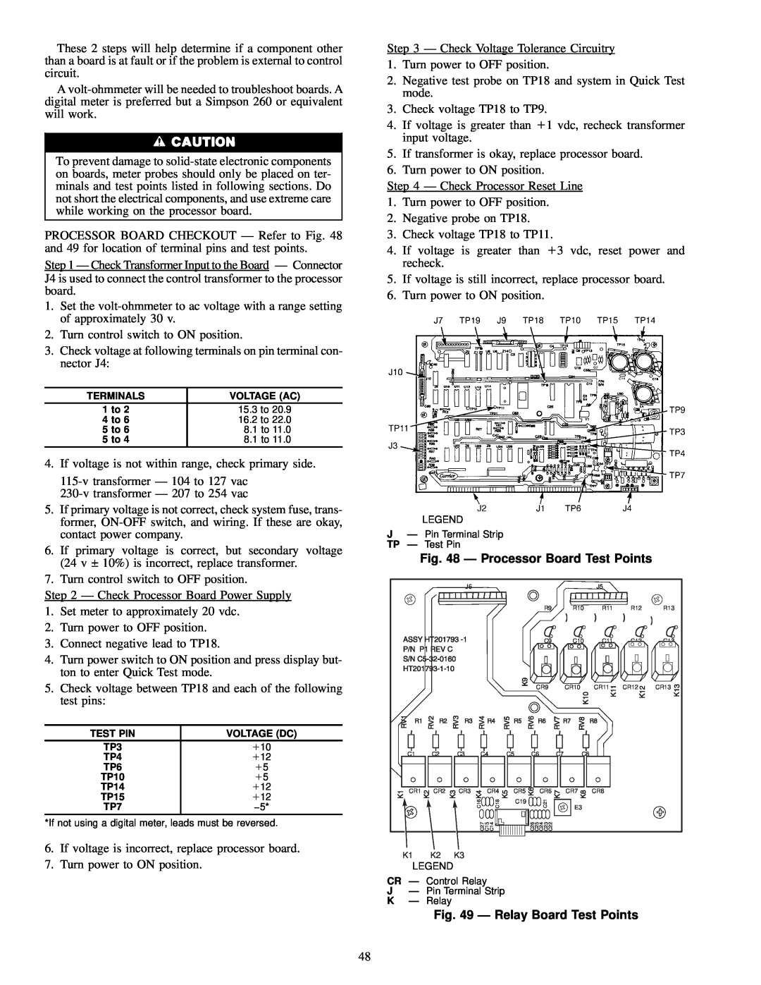
LEGEND
JÐ Pin Terminal Strip TP Ð Test Pin
Fig. 48 Ð Processor Board Test Points
|
| J6 |
|
|
|
|
|
|
| J5 |
|
|
|
|
|
|
|
|
| R9 |
| R10 | R11 | R12 | R13 |
|
|
|
|
|
|
| C9 |
| C10 | C11 |
|
|
|
|
|
|
|
|
| CR9 |
| CR10 | CR11 | CR12 | CR13 |
C1 | C2 | C3 | C4 |
| C5 | C6 | C7 | C8 |
|
|
| |
CR1 | CR2 | CR3 |
| CR4 | CR5 | CR6 |
| CR7 | CR8 |
|
| |
|
| C16 |
|
| C18 | C19 | C21 |
| E3 |
|
|
|
|
|
|
|
|
|
|
|
| ||||
|
|
|
|
|
|
|
|
|
|
|
| |
|
| C27 | C15 | C14 |
| C26 C25 C24 C23 C22 |
|
|
|
|
| |
K1 | K2 | K3 |
|
|
|
|
|
|
|
|
|
|
LEGEND |
|
|
|
|
|
|
|
|
|
|
| |
CR Ð Control Relay
JÐ Pin Terminal Strip
KÐ Relay
Fig. 49 Ð Relay Board Test Points
48