|
| LEGEND |
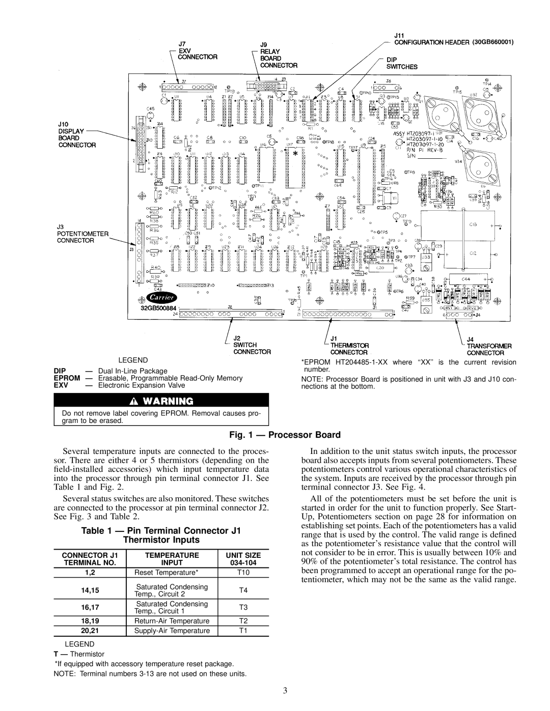
DIP | Ð | Dual |
EPROM Ð Erasable, Programmable | ||
EXV | Ð | Electronic Expansion Valve |
Do not remove label covering EPROM. Removal causes pro- gram to be erased.
*EPROM
NOTE: Processor Board is positioned in unit with J3 and J10 con- nections at the bottom.
Fig. 1 Ð Processor Board
Several temperature inputs are connected to the proces- sor. There are either 4 or 5 thermistors (depending on the
Several status switches are also monitored. These switches are connected to the processor at pin terminal connector J2. See Fig. 3 and Table 2.
Table 1 Ð Pin Terminal Connector J1
Thermistor Inputs
CONNECTOR J1 | TEMPERATURE | UNIT SIZE | |
TERMINAL NO. | INPUT | ||
1,2 | Reset Temperature* | T10 | |
14,15 | Saturated Condensing | T4 | |
Temp., Circuit 2 | |||
|
| ||
16,17 | Saturated Condensing | T3 | |
Temp., Circuit 1 | |||
|
| ||
18,19 | T2 | ||
20,21 | T1 |
LEGEND
T Ð Thermistor
*If equipped with accessory temperature reset package. NOTE: Terminal numbers
In addition to the unit status switch inputs, the processor board also accepts inputs from several potentiometers. These potentiometers control various operational characteristics of the system. Inputs are received by the processor through pin terminal connector J3. See Fig. 4.
All of the potentiometers must be set before the unit is started in order for the unit to function properly. See Start- Up, Potentiometers section on page 28 for information on establishing set points. Each of the potentiometers has a valid range that is used by the control. The valid range is de®ned as the potentiometer's resistance value that the control will not consider to be in error. This is usually between 10% and 90% of the potentiometer's total resistance. The control has been programmed to accept an operational range for the po- tentiometer, which may not be the same as the valid range.
3