P1 SUPPLY AIR |
| DISPLAY | ||||||||||
SET POINT |
| DISPLAY | BUTTON | |||||||||
POTENTIOMETER |
|
|
|
|
|
|
|
|
|
|
| |
|
|
|
|
|
|
|
|
|
|
|
|
|
|
|
|
|
|
|
|
|
|
|
|
|
|
|
|
|
|
|
|
|
|
|
|
|
|
|
|
|
|
|
|
|
|
|
|
|
|
|
|
|
|
|
|
|
|
|
|
|
|
|
|
|
|
|
|
|
|
|
|
|
|
|
|
|
|
|
|
|
|
|
|
|
|
|
|
|
|
|
|
|
|
|
|
|
|
|
|
|
|
|
|
|
|
|
|
|
|
|
|
|
|
|
|
|
|
|
|
|
|
|
|
|
|
|
|
|
|
|
|
|
|
|
|
|
|
|
|
|
|
|
|
|
|
|
|
|
|
|
|
|
|
|
|
|
|
|
|
|
|
|
|
|
|
|
|
|
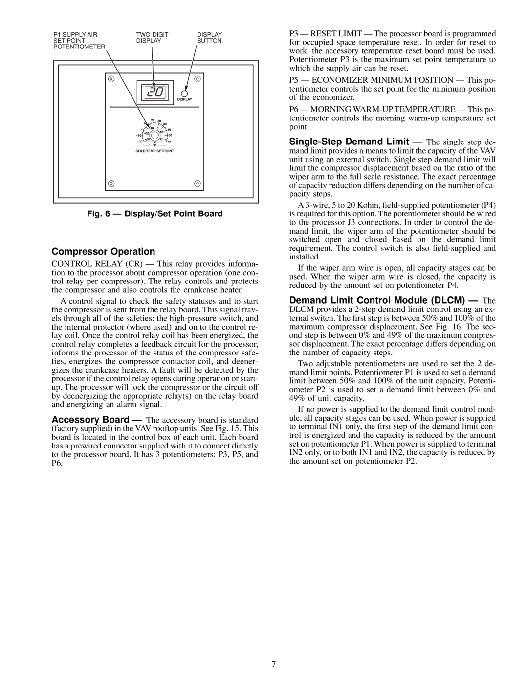
Fig. 6 Ð Display/Set Point Board
Compressor Operation
CONTROL RELAY (CR) Ð This relay provides informa- tion to the processor about compressor operation (one con- trol relay per compressor). The relay controls and protects the compressor and also controls the crankcase heater.
A control signal to check the safety statuses and to start the compressor is sent from the relay board. This signal trav- els through all of the safeties: the
Accessory Board Ð The accessory board is standard (factory supplied) in the VAV rooftop units. See Fig. 15. This board is located in the control box of each unit. Each board has a prewired connector supplied with it to connect directly to the processor board. It has 3 potentiometers: P3, P5, and P6.
P3 Ð RESET LIMIT Ð The processor board is programmed for occupied space temperature reset. In order for reset to work, the accessory temperature reset board must be used. Potentiometer P3 is the maximum set point temperature to which the supply air can be reset.
P5 Ð ECONOMIZER MINIMUM POSITION Ð This po- tentiometer controls the set point for the minimum position of the economizer.
P6 Ð MORNING
A
If the wiper arm wire is open, all capacity stages can be used. When the wiper arm wire is closed, the capacity is reduced by the amount set on potentiometer P4.
Demand Limit Control Module (DLCM) Ð The DLCM provides a
Two adjustable potentiometers are used to set the 2 de- mand limit points. Potentiometer P1 is used to set a demand limit between 50% and 100% of the unit capacity. Potenti- ometer P2 is used to set a demand limit between 0% and 49% of unit capacity.
If no power is supplied to the demand limit control mod- ule, all capacity stages can be used. When power is supplied to terminal IN1 only, the ®rst step of the demand limit con- trol is energized and the capacity is reduced by the amount set on potentiometer P1. When power is supplied to terminal IN2 only, or to both IN1 and IN2, the capacity is reduced by the amount set on potentiometer P2.
7