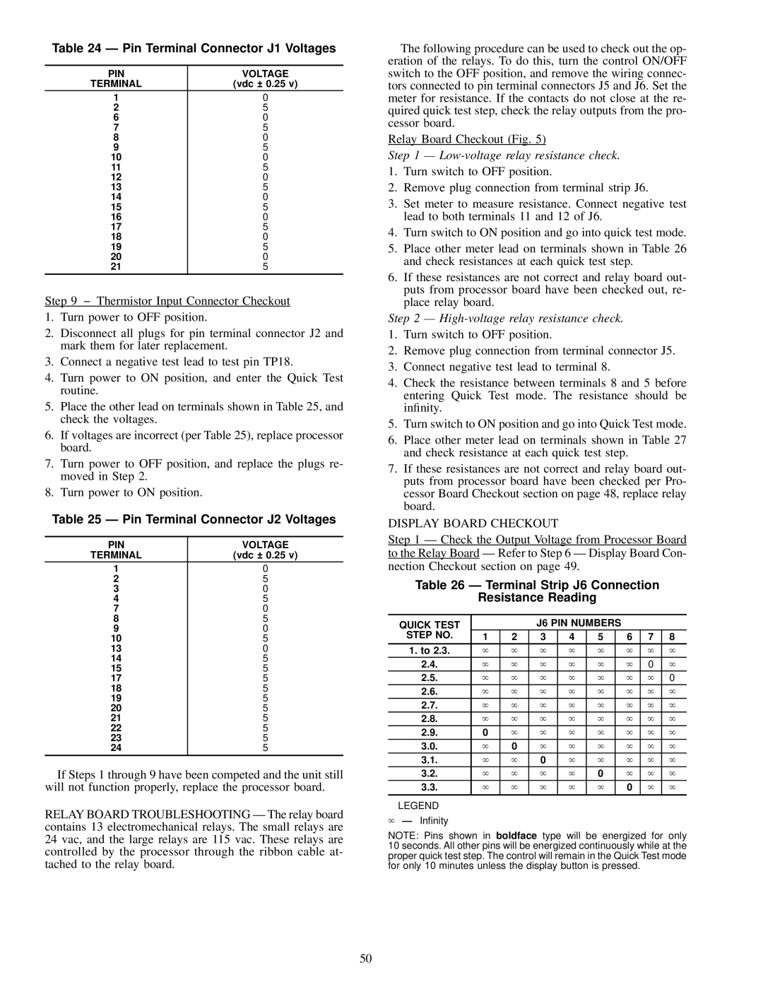
Table 24 Ð Pin Terminal Connector J1 Voltages
PIN | VOLTAGE |
TERMINAL | (vdc ± 0.25 v) |
1 | 0 |
2 | 5 |
6 | 0 |
7 | 5 |
8 | 0 |
9 | 5 |
10 | 0 |
11 | 5 |
12 | 0 |
13 | 5 |
14 | 0 |
15 | 5 |
16 | 0 |
17 | 5 |
18 | 0 |
19 | 5 |
20 | 0 |
21 | 5 |
Step 9 − Thermistor Input Connector Checkout
1.Turn power to OFF position.
2.Disconnect all plugs for pin terminal connector J2 and mark them for later replacement.
3.Connect a negative test lead to test pin TP18.
4.Turn power to ON position, and enter the Quick Test routine.
5.Place the other lead on terminals shown in Table 25, and check the voltages.
6.If voltages are incorrect (per Table 25), replace processor board.
7.Turn power to OFF position, and replace the plugs re- moved in Step 2.
8.Turn power to ON position.
Table 25 Ð Pin Terminal Connector J2 Voltages
PIN | VOLTAGE |
TERMINAL | (vdc ± 0.25 v) |
1 | 0 |
2 | 5 |
3 | 0 |
4 | 5 |
7 | 0 |
8 | 5 |
9 | 0 |
10 | 5 |
13 | 0 |
14 | 5 |
15 | 5 |
17 | 5 |
18 | 5 |
19 | 5 |
20 | 5 |
21 | 5 |
22 | 5 |
23 | 5 |
24 | 5 |
If Steps 1 through 9 have been competed and the unit still will not function properly, replace the processor board.
RELAY BOARD TROUBLESHOOTING Ð The relay board contains 13 electromechanical relays. The small relays are 24 vac, and the large relays are 115 vac. These relays are controlled by the processor through the ribbon cable at- tached to the relay board.
The following procedure can be used to check out the op- eration of the relays. To do this, turn the control ON/OFF switch to the OFF position, and remove the wiring connec- tors connected to pin terminal connectors J5 and J6. Set the meter for resistance. If the contacts do not close at the re- quired quick test step, check the relay outputs from the pro- cessor board.
Relay Board Checkout (Fig. 5)
Step 1 Ð Low-voltage relay resistance check.
1.Turn switch to OFF position.
2.Remove plug connection from terminal strip J6.
3.Set meter to measure resistance. Connect negative test lead to both terminals 11 and 12 of J6.
4.Turn switch to ON position and go into quick test mode.
5.Place other meter lead on terminals shown in Table 26 and check resistances at each quick test step.
6.If these resistances are not correct and relay board out- puts from processor board have been checked out, re- place relay board.
Step 2 Ð High-voltage relay resistance check.
1.Turn switch to OFF position.
2.Remove plug connection from terminal connector J5.
3.Connect negative test lead to terminal 8.
4.Check the resistance between terminals 8 and 5 before entering Quick Test mode. The resistance should be in®nity.
5.Turn switch to ON position and go into Quick Test mode.
6.Place other meter lead on terminals shown in Table 27 and check resistance at each quick test step.
7.If these resistances are not correct and relay board out- puts from processor board have been checked per Pro- cessor Board Checkout section on page 48, replace relay board.
DISPLAY BOARD CHECKOUT
Step 1 Ð Check the Output Voltage from Processor Board to the Relay Board Ð Refer to Step 6 Ð Display Board Con- nection Checkout section on page 49.
Table 26 Ð Terminal Strip J6 Connection
Resistance Reading
QUICK TEST |
|
| J6 PIN NUMBERS |
|
|
| |||
STEP NO. | 1 | 2 | 3 | 4 | 5 |
| 6 | 7 | 8 |
1. to 2.3. | ` | ` | ` | ` | ` |
| ` | ` | ` |
2.4. | ` | ` | ` | ` | ` |
| ` | 0 | ` |
2.5. | ` | ` | ` | ` | ` |
| ` | ` | 0 |
2.6. | ` | ` | ` | ` | ` |
| ` | ` | ` |
2.7. | ` | ` | ` | ` | ` |
| ` | ` | ` |
2.8. | ` | ` | ` | ` | ` |
| ` | ` | ` |
2.9. | 0 | ` | ` | ` | ` |
| ` | ` | ` |
3.0. | ` | 0 | ` | ` | ` |
| ` | ` | ` |
3.1. | ` | ` | 0 | ` | ` |
| ` | ` | ` |
3.2. | ` | ` | ` | ` | 0 |
| ` | ` | ` |
3.3. | ` | ` | ` | ` | ` |
| 0 | ` | ` |
|
|
|
|
|
|
|
|
|
|
LEGEND
` Ð In®nity
NOTE: Pins shown in boldface type will be energized for only 10 seconds. All other pins will be energized continuously while at the proper quick test step. The control will remain in the Quick Test mode for only 10 minutes unless the display button is pressed.
50