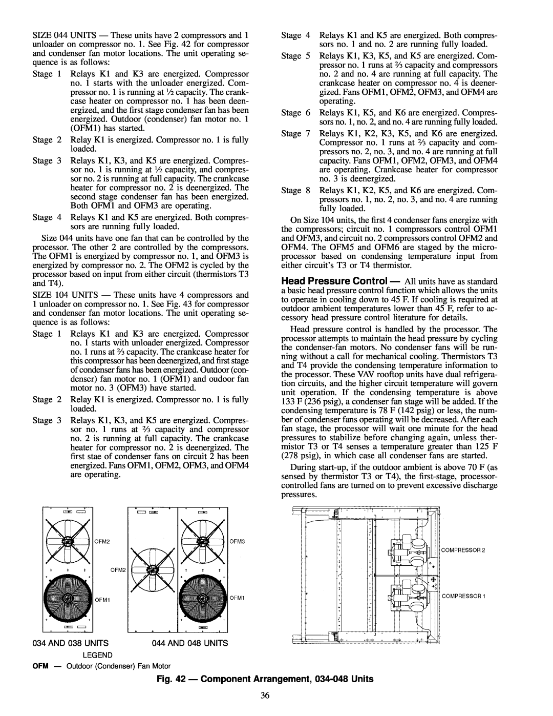
SIZE 044 UNITS Ð These units have 2 compressors and 1 unloader on compressor no. 1. See Fig. 42 for compressor and condenser fan motor locations. The unit operating se- quence is as follows:
Stage 1 Relays K1 and K3 are energized. Compressor no. 1 starts with the unloader energized. Com- pressor no. 1 is running at 1¤2 capacity. The crank- case heater on compressor no. 1 has been deen- ergized, and the ®rst stage condenser fan has been energized. Outdoor (condenser) fan motor no. 1 (OFM1) has started.
Stage 2 Relay K1 is energized. Compressor no. 1 is fully loaded.
Stage 3 Relays K1, K3, and K5 are energized. Compres- sor no. 1 is running at 1¤2 capacity, and compres- sor no. 2 is running at full capacity. The crankcase heater for compressor no. 2 is deenergized. The second stage condenser fan has been energized. Both OFM1 and OFM3 are operating.
Stage 4 Relays K1 and K5 are energized. Both compres- sors are running fully loaded.
Size 044 units have one fan that can be controlled by the processor. The other 2 are controlled by the compressors. The OFM1 is energized by compressor no. 1, and OFM3 is energized by compressor no. 2. The OFM2 is cycled by the processor based on input from either circuit (thermistors T3 and T4).
SIZE 104 UNITS Ð These units have 4 compressors and 1 unloader on compressor no. 1. See Fig. 43 for compressor and condenser fan motor locations. The unit operating se- quence is as follows:
Stage 1 Relays K1 and K3 are energized. Compressor no. 1 starts with unloader energized. Compressor no. 1 runs at 2¤3 capacity. The crankcase heater for this compressor has been deenergized, and ®rst stage of condenser fans has been energized. Outdoor (con- denser) fan motor no. 1 (OFM1) and oudoor fan motor no. 3 (OFM3) have started.
Stage 2 Relay K1 is energized. Compressor no. 1 is fully loaded.
Stage 3 Relays K1, K3, and K5 are energized. Compres- sor no. 1 runs at 2¤3 capacity and compressor no. 2 is running at full capacity. The crankcase heater for compressor no. 2 is deenergized. The ®rst stae of condenser fans on circuit 2 has been energized. Fans OFM1, OFM2, OFM3, and OFM4 are operating.
Stage 4 Relays K1 and K5 are energized. Both compres- sors no. 1 and no. 2 are running fully loaded.
Stage 5 Relays K1, K3, K5, and K5 are energized. Com- pressor no. 1 runs at 2¤3 capacity and compressors no. 2 and no. 4 are running at full capacity. The crankcase heater on compressor no. 4 is deener- gized. Fans OFM1, OFM2, OFM3, and OFM4 are operating.
Stage 6 Relays K1, K5, and K6 are energized. Compres- sors no. 1, no. 2, and no. 4 are running fully loaded.
Stage 7 Relays K1, K2, K3, K5, and K6 are energized. Compressor no. 1 runs at 2¤3 capacity and com- pressors no. 2, no. 3, and no. 4 are running at full capacity. Fans OFM1, OFM2, OFM3, and OFM4 are operating. Crankcase heater for compressor no. 3 is deenergized.
Stage 8 Relays K1, K2, K5, and K6 are energized. Com- pressors no. 1, no. 2, no. 3, and no. 4 are running fully loaded.
On Size 104 units, the ®rst 4 condenser fans energize with the compressors; circuit no. 1 compressors control OFM1 and OFM3, and circuit no. 2 compressors control OFM2 and OFM4. The OFM5 and OFM6 are staged by the micro- processor based on condensing temperature input from either circuit's T3 or T4 thermistor.
Head Pressure Control Ð All units have as standard a basic head pressure control function which allows the units to operate in cooling down to 45 F. If cooling is required at outdoor ambient temperatures lower than 45 F, refer to ac- cessory head pressure control literature for details.
Head pressure control is handled by the processor. The processor attempts to maintain the head pressure by cycling the
During
034 AND 038 UNITS | 044 AND 048 UNITS |
LEGEND
OFM Ð Outdoor (Condenser) Fan Motor
Fig. 42 Ð Component Arrangement, 034-048 Units
36