a50-8160
|
|
| LEGEND |
|
|
|
|
|
|
|
|
|
|
|
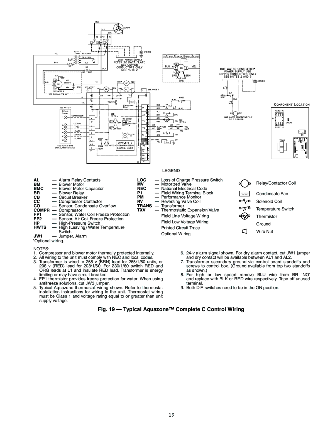
AL | — Alarm Relay Contacts | LOC | — Loss of Charge Pressure Switch |
|
|
|
|
|
|
|
|
| Relay/Contactor Coil | |
BM | — Blower Motor | MV | — Motorized Valve |
|
|
|
|
|
|
|
|
| ||
BMC | — Blower Motor Capacitor | NEC | — National Electrical Code |
|
|
|
|
|
|
|
|
|
| |
BR | — Blower Relay | P1 | — Field Wiring Terminal Block |
|
|
|
|
|
|
|
|
| Condensate Pan | |
|
|
|
|
|
|
|
|
| ||||||
|
|
|
|
|
|
|
|
| ||||||
CB | — Circuit Breaker | PM | — Performance Monitor |
|
|
|
|
|
|
|
|
|
| |
CC | — Compressor Contactor | RV | — Reversing Valve Coil |
|
|
|
|
|
|
|
|
| Solenoid Coil | |
CO | — Sensor, Condensate Overflow | TRANS — Transformer |
|
|
|
|
|
|
|
|
| Temperature Switch | ||
COMPR | — Compressor | TXV | — Thermostatic Expansion Valve |
|
|
|
|
|
|
|
|
| ||
FP1 | — Sensor, Water Coil Freeze Protection |
| Field Line Voltage Wiring |
|
|
|
|
|
|
|
|
| Thermistor | |
FP2 | — Sensor, Air Coil Freeze Protection |
|
|
|
|
|
|
|
|
|
| |||
|
|
|
|
|
|
|
|
|
| |||||
| Field Low Voltage Wiring |
|
|
|
|
|
|
|
|
|
| |||
HP | — |
|
|
|
|
|
|
|
|
|
| Ground | ||
HWTS | — High (Leaving) Water Temperature |
| Printed Circuit Trace |
|
|
|
|
|
|
|
|
| Wire Nut | |
| Switch |
| Optional Wiring |
|
|
|
|
|
|
|
|
| ||
JW1 | — Jumper, Alarm |
|
|
|
|
|
|
|
|
|
|
| ||
|
|
|
|
|
|
|
|
|
|
|
|
| ||
*Optional wiring. |
|
|
|
|
|
|
|
|
|
|
|
|
| |
NOTES: |
|
|
|
|
|
|
|
|
|
|
|
|
|
|
1. Compressor and blower motor thermally protected internally. |
| 6. | ||||||||||||
2. All wiring to the unit must comply with NEC and local codes. |
| and dry contact will be available between AL1 and AL2. | ||||||||||||
3. Transformer is wired to 265 v (BRN) lead for 265/1/60 units, or | 7. Transformer secondary ground via control board standoffs and | |||||||||||||
208 v (RED) lead for 208/1/60. For 230/1/60 switch RED and | screws to control box. (Ground available from top two standoffs | |||||||||||||
ORG leads at L1 and insulate RED lead. Transformer is energy | as shown.) |
|
|
|
|
|
|
|
|
|
| |||
limiting or may have circuit breaker. |
|
| 8. For high or low speed | remove BLU wire from BR ‘NO’ | ||||||||||
4. FP1 thermistor provides freeze protection for water. When using | and replace with BLK or RED wire respectively. Tape off unused | |||||||||||||
antifreeze solutions, cut JW3 jumper. |
|
| terminal. |
|
|
|
|
|
|
|
|
|
| |
5. Typical Aquazone thermostat wiring shown. Refer to thermostat | 9. Both DIP switches need to be in the ON position. | |||||||||||||
installation instructions for wiring to the unit. Thermostat wiring |
|
|
|
|
|
|
|
|
|
|
| |||
must be Class 1 and voltage rating equal to or greater than unit |
|
|
|
|
|
|
|
|
|
|
| |||
supply voltage. |
|
|
|
|
|
|
|
|
|
|
|
|
| |
Fig. 19 — Typical Aquazone™ Complete C Control Wiring
19