compressor application, all compressor relays and related func- tions will track with their associated DIP switch 2 on S1.
NIGHT LOW LIMIT (NLL) STAGED HEATING — In NLL staged Heating mode, the override (OVR) input becomes active and is recognized as a call for heating and the control will immediately go into a Heating Stage 1 mode. With an ad- ditional 30 minutes of NLL demand, the control will go into Heating Stage 2 mode. With another additional 30 minutes of NLL demand, the control will go into Heating Stage 3 mode.
Units with HWR Option
FAN ONLY — A (G) call from the thermostat to the (G) terminal of the Deluxe D control board will bring the unit on in fan only mode.
COOLING STAGE 1 — A simultaneous call from (G), (Y1), and (O) to the (G), (Y1), (O/W2) terminals of the Deluxe D control board will bring the unit on in 1st Stage Cooling.
COOLING STAGE 2 — A simultaneous call from (G), (Y1), (Y2), and (O) to the (G), (Y1), (Y2), and (O/W2) ter- minals of the Deluxe D control board will bring the unit on in Cooling Stage 2. When the call is satisfied at the thermo- stat the unit will continue to run in Cooling Stage 1 until the Cooling Stage 1 call is removed or satisfied, shutting down the unit.
NOTE: Not all units have
HEATING STAGE 1 — A simultaneous call from (G) and (Y1) to the (G) and (Y1) terminals of the Deluxe D control board will bring the unit on in Heating Stage 1.
HEATING STAGE 2 — A simultaneous call from (G), (Y1), and (Y2) to the (G), (Y1), and (Y2) terminals of the Deluxe D control board will bring the unit on in Heating Stage 2. When the call is satisfied at the thermostat the unit will continue to run in Heating Stage 1 until the call is removed or satisfied, shutting down the unit.
NOTE: Not all units have
REHEAT MODE — A call from the humidistat/dehumid- istat to the (H) terminal of the Deluxe D control board will bring the unit on in Reheat Mode if there is no call for cool- ing at the thermostat. When the humidistat/dehumidistat call is removed or satisfied the unit will shut down.
NOTE: Cooling always overrides Reheat Mode. In the Cool- ing mode, the unit cools and dehumidifies. If the cooling thermostat is satisfied but there is still a call for dehumidifi- cation, the unit will continue to operate in Reheat Mode.
SYSTEM TEST
System testing provides the ability to check the control operation. The control enters a
Test Mode — To enter Test mode on Complete C or Deluxe D controls, cycle the power 3 times within 60 seconds. The LED
NOTE: Deluxe D Control has a flashing code and alarm relay cycling code that will both have the same numerical label. For example, flashing code 1 will have an alarm relay cycling code 1. Code 1 indicates the control has not faulted since the last power off to power on sequence.
Retry Mode — In Retry mode, the status LED will start to flash slowly to signal that the control is trying to recover from an input fault. The control will stage off the outputs and try to again satisfy the thermostat used to terminal Y. Once the ther- mostat input calls are satisfied, the control will continue normal operation.
NOTE: If 3 consecutive faults occur without satisfying the thermostat input call to terminal Y, the control will go into lockout mode. The last fault causing the lockout is stored in memory and can be viewed by entering Test mode.
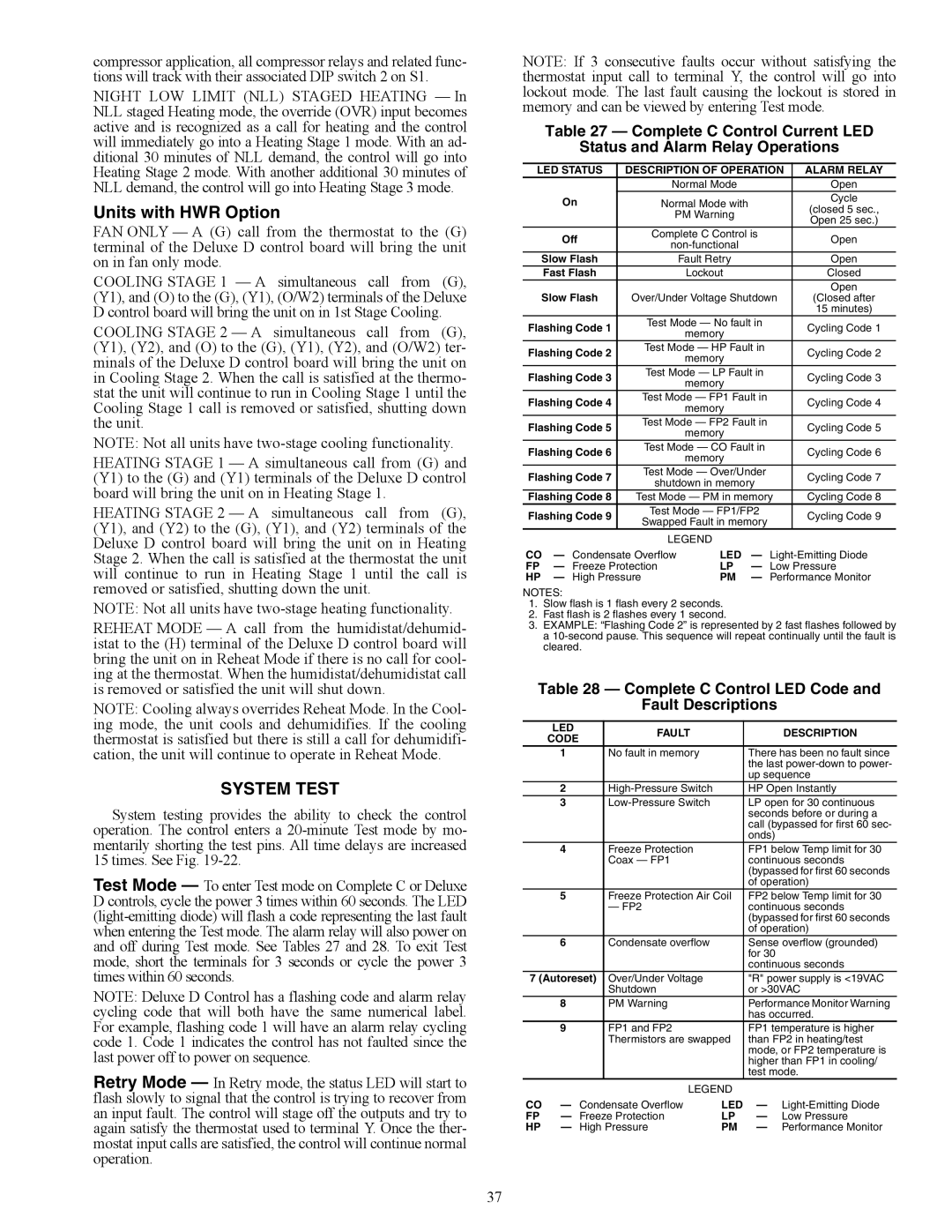
Table 27 — Complete C Control Current LED
Status and Alarm Relay Operations
LED STATUS | DESCRIPTION OF OPERATION | ALARM RELAY | ||||
|
| Normal Mode |
| Open | ||
| On | Normal Mode with |
| Cycle | ||
|
| (closed 5 sec., | ||||
|
| PM Warning |
| |||
|
|
| Open 25 sec.) | |||
|
|
|
|
| ||
| Off | Complete C Control is | Open | |||
|
| |||||
|
|
|
| |||
Slow Flash |
| Fault Retry |
| Open | ||
| Fast Flash |
| Lockout |
| Closed | |
Slow Flash |
|
|
| Open | ||
Over/Under Voltage Shutdown | (Closed after | |||||
|
|
|
|
| 15 minutes) | |
Flashing Code 1 | Test Mode — No fault in | Cycling Code 1 | ||||
| memory |
| ||||
|
|
|
|
| ||
Flashing Code 2 | Test Mode — HP Fault in | Cycling Code 2 | ||||
| memory |
| ||||
|
|
|
|
| ||
Flashing Code 3 | Test Mode — LP Fault in | Cycling Code 3 | ||||
| memory |
| ||||
|
|
|
|
| ||
Flashing Code 4 | Test Mode — FP1 Fault in | Cycling Code 4 | ||||
| memory |
| ||||
|
|
|
|
| ||
Flashing Code 5 | Test Mode — FP2 Fault in | Cycling Code 5 | ||||
| memory |
| ||||
|
|
|
|
| ||
Flashing Code 6 | Test Mode — CO Fault in | Cycling Code 6 | ||||
| memory |
| ||||
|
|
|
|
| ||
Flashing Code 7 | Test Mode — Over/Under | Cycling Code 7 | ||||
shutdown in memory | ||||||
|
|
| ||||
Flashing Code 8 | Test Mode — PM in memory | Cycling Code 8 | ||||
Flashing Code 9 | Test Mode — FP1/FP2 | Cycling Code 9 | ||||
Swapped Fault in memory | ||||||
|
|
| ||||
|
| LEGEND |
|
| ||
CO | — Condensate Overflow | LED | — | |||
FP | — Freeze Protection | LP | — Low Pressure | |||
HP | — High Pressure | PM | — Performance Monitor | |||
NOTES:
1.Slow flash is 1 flash every 2 seconds.
2.Fast flash is 2 flashes every 1 second.
3.EXAMPLE: “Flashing Code 2” is represented by 2 fast flashes followed by a
Table 28 — Complete C Control LED Code and
Fault Descriptions
| LED | FAULT |
|
| DESCRIPTION |
| CODE |
|
| ||
|
|
|
|
| |
| 1 | No fault in memory |
| There has been no fault since | |
|
|
|
| the last | |
|
|
|
| up sequence | |
| 2 |
| HP Open Instantly | ||
| 3 |
| LP open for 30 continuous | ||
|
|
|
| seconds before or during a | |
|
|
|
| call (bypassed for first 60 sec- | |
|
|
|
| onds) |
|
| 4 | Freeze Protection |
| FP1 below Temp limit for 30 | |
|
| Coax — FP1 |
| continuous seconds | |
|
|
|
| (bypassed for first 60 seconds | |
|
|
|
| of operation) | |
| 5 | Freeze Protection Air Coil | FP2 below Temp limit for 30 | ||
|
| — FP2 |
| continuous seconds | |
|
|
|
| (bypassed for first 60 seconds | |
|
|
|
| of operation) | |
| 6 | Condensate overflow |
| Sense overflow (grounded) | |
|
|
|
| for 30 |
|
|
|
|
| continuous seconds | |
7 (Autoreset) | Over/Under Voltage |
| "R" power supply is <19VAC | ||
|
| Shutdown |
| or >30VAC | |
| 8 | PM Warning |
| Performance Monitor Warning | |
|
|
|
| has occurred. | |
| 9 | FP1 and FP2 |
| FP1 temperature is higher | |
|
| Thermistors are swapped | than FP2 in heating/test | ||
|
|
|
| mode, or FP2 temperature is | |
|
|
|
| higher than FP1 in cooling/ | |
|
|
|
| test mode. | |
|
| LEGEND |
|
| |
CO | — Condensate Overflow | LED | — | ||
FP | — Freeze Protection | LP | — | Low Pressure | |
HP | — High Pressure | PM | — | Performance Monitor | |
37