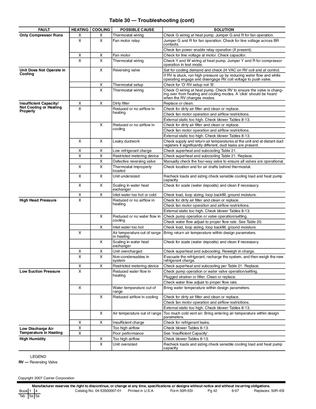
Table 30 — Troubleshooting (cont)
FAULT | HEATING | COOLING | POSSIBLE CAUSE | SOLUTION |
Only Compressor Runs | X | X | Thermostat wiring | Check G wiring at heat pump. Jumper G and R for fan operation. |
| X | X | Fan motor relay | Jumper G and R for fan operation. Check for line voltage across BR |
|
|
|
| contacts. |
|
|
|
| Check fan power enable relay operation (if present). |
| X | X | Fan motor | Check for line voltage at motor. Check capacitor. |
| X | X | Thermostat wiring | Check Y and W wiring at heat pump. Jumper Y and R for compressor |
|
|
|
| operation in test mode. |
Unit Does Not Operate in |
| X | Reversing valve | Set for cooling demand and check 24 VAC on RV coil and at control. |
Cooling |
|
|
|
|
|
|
| If RV is stuck, run high pressure up by reducing water flow and while | |
|
|
|
| |
|
|
|
| operating engage and disengage RV coil voltage to push valve. |
|
| X | Thermostat setup | Check for 'O' RV setup not 'B'. |
|
| X | Thermostat wiring | Check O wiring at heat pump. Check RV to ensure the valve is chang- |
|
|
|
| ing over from heating and cooling modes. A 'click' should be heard |
|
|
|
| when the RV changes modes. |
Insufficient Capacity/ | X | X | Dirty filter | Replace or clean. |
Not Cooling or Heating |
|
|
|
|
X |
| Reduced or no airflow in | Check for dirty air filter and clean or replace. | |
Properly |
| |||
|
| heating |
| |
|
| Check fan motor operation and airflow restrictions. | ||
|
|
| ||
|
|
|
| |
|
|
|
| External static too high. Check blower Tables |
|
| X | Reduced or no airflow in | Check for dirty air filter and clean or replace. |
|
|
| cooling |
|
|
|
| Check fan motor operation and airflow restrictions. | |
|
|
|
| |
|
|
|
| External static too high. Check blower Tables |
| X | X | Leaky ductwork | Check supply and return air temperatures at the unit and at distant duct |
|
|
|
| registers if significantly different, duct leaks are present. |
| X | X | Low refrigerant charge | Check superheat and subcooling Table 21. |
| X | X | Restricted metering device | Check superheat and subcooling Table 21. Replace. |
|
| X | Defective reversing valve | Manually check the |
| X | X | Thermostat improperly | Check location and for air drafts behind thermostat. |
|
|
| located |
|
| X | X | Unit undersized | Recheck loads and sizing check sensible cooling load and heat pump |
|
|
|
| capacity. |
| X | X | Scaling in water heat | Check for scale (water deposits) and clean if necessary. |
|
|
| exchanger |
|
| X | X | Inlet water too hot or cold | Check load, loop sizing, loop backfill, ground moisture. |
High Head Pressure | X |
| Reduced or no airflow in | Check for dirty air filter and clean or replace. |
|
|
| heating | Check fan motor operation and airflow restrictions. |
|
|
|
| |
|
|
|
| External static too high. Check blower Tables |
|
| X | Reduced or no water flow in | Check pump operation or valve operation/setting. |
|
|
| cooling |
|
|
|
| Check water flow adjust to proper flow rate. See Table 20. | |
|
|
|
| |
|
| X | Inlet water too hot | Check load, loop sizing, loop backfill, ground moisture. |
| X |
| Air temperature out of range | Bring return air temperature within design parameters. |
|
|
| in heating |
|
|
| X | Scaling in water heat | Check for scale (water deposits) and clean if necessary. |
|
|
| exchanger |
|
| X | X | Unit overcharged | Check superheat and subcooling. Reweigh in charge. |
| X | X | Evacuate the refrigerant, recharge the system, and then weigh the new | |
|
|
| system | refrigerant charge. |
| X | X | Restricted metering device | Check superheat and subcooling per Table 21. Replace. |
Low Suction Pressure | X |
| Reduced water flow in | Check pump operation or water valve operation/setting. |
|
|
| heating | Plugged strainer or filter. Clean or replace. |
|
|
|
| |
|
|
|
| Check water flow adjust to proper flow rate. |
| X |
| Water temperature out of | Bring water temperature within design parameters. |
|
|
| range |
|
|
| X | Reduced airflow in cooling | Check for dirty air filter and clean or replace. |
|
|
|
| Check fan motor operation and airflow restrictions. |
|
|
|
| External static too high. Check blower Tables |
|
| X | Air temperature out of range | Too much cold vent air. Bring entering air temperature within design |
|
|
|
| parameters. |
| X | X | Insufficient charge | Check for refrigerant leaks. |
Low Discharge Air | X |
| Too high airflow | Check blower Tables |
Temperature in Heating | X |
| Poor performance | See 'Insufficient Capacity'. |
High Humidity |
| X | Too high airflow | Check blower Tables |
|
| X | Unit oversized | Recheck loads and sizing check sensible cooling load and heat pump |
|
|
|
| capacity. |
LEGEND |
|
|
|
|
RV — Reversing Valve |
|
|
|
|
Copyright 2007 Carrier Corporation
Manufacturer reserves the right to discontinue, or change at any time, specifications or designs without notice and without incurring obligations.
Book | 1 | 4 | Catalog No. | Form | Pg 42 | Replaces: | |
Tab | 5a | 5a |
|
|
|
|
|
|
|
|
|
|
|
|
|