Safety Considerations
Contents
General
Installation
Page
PSC FAN Motor and Blower
Physical Data Aquazone 50RHC,RVC006-060 Units
Physical Data Aquazone 50RHR,RVR006-060 Units
Physical Data Aquazone 50RHS,RVS,RDS015-070 Units
Permanent Split Capacitor
Airflow Configuration
Code Return Discharge
Right
Depth Height Out Pump Supply Ensate
Ext Power Cond Therm Supply Return
015-024
030
Right Back
Back Right
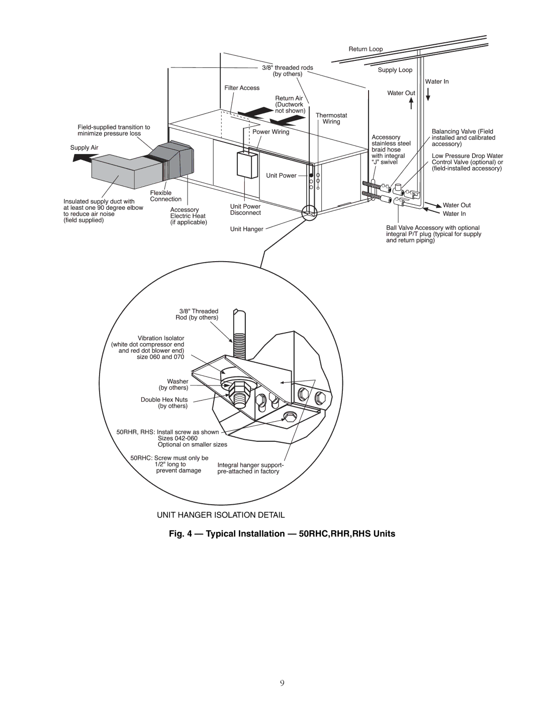
Typical Installation 50RHC,RHR,RHS Units
Right Top
Top
Configuration Left Return Left View
Configuration Top View-Left Return
Isometric
View
Isometric View
Configuration Left Return Left View Air Coil Opening
Code
Front View
Return/Bottom Discharge Isometric View
Ht Return/Bottom Discharge
Top View
Front-View
Side Discharge
Remove Screws
Rotate
Move to Side
50RHC Units
Mounting the Unit
50RHR Units
50RHS Units
Horizontal Unit Pitch
Condensate Drain
Condition Acceptable Level
Field Control Wiring
Field Power Supply Wiring
BMC
LOC
NEC
Compr
RVS
Typical Aquazone Deluxe D Control Wiring
Hpws
LON
Trans
A50-8154
Low Voltage Field Wiring
RLA LRA Motor Unit Circuit FUSE/HACR
50RHC,RVC Electrical Data
FLA
RLA
50RHR,RVR Electrical Data
50RHR,RVR VOLTS-PHASE Voltage Compressor FAN Total MIN MAX
Unit Circuit Units
RLA LRA FUSE/HACR
50RDS, RHS, RVS Electrical Data
PRE-START-UP
50RHR,RVR Blower Performance
50RHR,RVR Rated MIN FAN
Speed
50RVC Blower Performance with Hot Water Reheat HWR Option
50RHC,RVC Blower Performance
Reheat External Static Pressure ESP Loss Coil Face Velocity
50RHC,RVC Rated MIN FAN
50RHS,RVS,RDS Blower Performance
50RVC Blower Performance with Wet Coil
Coil Face Velocity WET Coil Reduction
50RHS,RVS,RDS Rated FAN
Field Selectable Inputs
Control Jumper Settings See Fig
50RHS, RVS Blower Performance with HWR
Coil Face 50RHS, RVS with Reheat ESP Loss
DIP Switch Block S2 Accessory 2 Relay Options
DIP Switch Block S2 Accessory 1 Relay Options
Humidistat/Dehumidistat Logic Deluxe D DIP Switch Settings
Accessory DIP Switch Position Relay Options
START-UP
Control Accessory Relay Configurations
HWR Operating Modes
Output
Water Temperature Change Through Heat Exchanger
Unit Start-Up Cooling Mode
Operating Limits
Operating Limits 50RHC,RVC Units
Typical Unit Operating Pressures and Temperatures
Unit Start-Up Heating Mode
Entering Cooling Heating Water GPM
Temp F TON
50RHR,RVR Coaxial Water Pressure Drop
50RHS,RVS,RDS Coaxial Water Pressure Drop
50RHC,RVC Coaxial Water Pressure Drop
Antifreeze Percentages by Volume
Approximate Fluid Volume gal Per 100 Ft of Pipe
Operation
Units with Aquazone Complete C Control
Complete C Control LED Code Fault Descriptions
Units with HWR Option
System Test
Service
Aquazone Deluxe D Control LED Indica
ESD
Gravity Flow Method
Troubleshooting
Refrigerant Charging
Air Coil Fan Motor Removal
Fault Heating Cooling Possible Cause Solution
Troubleshooting
Unit Does Not Operate
II. START-UP
50RHC,RVC,RHR,RHS,RVR,RVS,RDS START-UP Checklist
Cooling Cycle Analysis
Heating Cycle Analysis