boilerless operation mode, only the compressor is used for heating when FP1 is above the boilerless changeover tempera- ture set by switch 8 below. Select ON for normal operation or select OFF for boilerless operation.
Boilerless Changeover Temperature — Switch 8 on S1 pro- vides selection of boilerless changeover temperature set point. Select OFF for set point of 50 F or select ON for set point of 40 F.
If switch 8 is set for 50 F, then the compressor will be used for heating as long as the FP1 is above 50 F. The compressor will not be used for heating when the FP1 is below 50 F and the compressor will operates in emergency heat mode, staging on EH1 and EH2 to provide heat. If a thermal switch is being used instead of the FP1 thermistor, only the compressor will be used for heating mode when the FP1 terminals are closed. If the FP1 terminals are open, the compressor is not used and the control goes into emergency heat mode.
DIP SWITCH BLOCK 2 (S2) — This set of DIP switches is used to configure accessory relay options. See Fig. 20.
Switches 1 to 3 — These DIP switches provide selection of Accessory 1 relay options. See Table 14 for DIP switch combinations.
Switches 4 to 6 — These DIP switches provide selection of Accessory 2 relay options. See Table 15 for DIP switch combinations.
Table 14 — DIP Switch Block S2 —
Accessory 1 Relay Options
ACCESSORY 1 | DIP SWITCH POSITION | ||
RELAY OPTIONS | 1 | 2 | 3 |
Cycle with Fan | On | On | On |
Digital NSB | Off | On | On |
Water Valve — Slow Opening | On | Off | On |
OAD | On | On | Off |
LEGEND |
|
|
|
NSB — Night Setback
OAD — Outside Air Damper
NOTE: All other DIP switch combinations are invalid.
Table 15 — DIP Switch Block S2 —
Accessory 2 Relay Options
ACCESSORY 2 | DIP SWITCH POSITION | ||
RELAY OPTIONS | 4 | 5 | 6 |
Cycle with Fan | On | On | On |
Digital NSB | Off | On | On |
Water Valve — Slow Opening | On | Off | On |
OAD | On | On | Off |
LEGEND |
|
|
|
NSB — Night Setback
OAD — Outside Air Damper
NOTE: All other switch combinations are invalid.
Auto Dehumidification Mode or High Fan Mode — Switch 7 provides selection of auto dehumidification fan mode or high fan mode. In auto dehumidification fan mode the fan speed relay will remain off during cooling stage 2 if terminal H is active. In high fan mode, the fan enable and fan speed relays will turn on when terminal H is active. Set the switch to ON for auto dehumidification fan mode or to OFF for high fan mode.
Switch 8 — Not used.
Units with Modulating Hot Water Reheat (HWR) Option — A heat pump equipped with Hot Water Reheat (HWR) can operate in three modes: cooling, cooling with reheat, and heating. The cooling and heating modes are like other Aquazone™ water source heat pumps. The reversing
valve ("O" signal) is energized in cooling, along with the com- pressor contactor(s) and blower relay. In the heating mode, the reversing valve is deenergized. Almost any thermostat will activate the heat pump in heating or cooling modes. The Deluxe D microprocessor board, which is standard with the HWR option, will accept either heat pump (Y,O) thermostats or
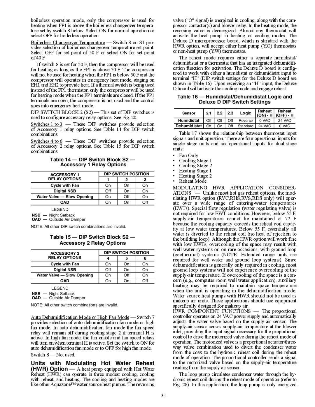
The reheat mode requires either a separate humidistat/ dehumidistat or a thermostat that has an integrated dehumidifi- cation function for activation. The Deluxe D board is config- ured to work with either a humidistat or dehumidistat input to terminal “H” (DIP switch settings for the Deluxe D board are shown in Table 16). Upon receiving an “H” input, the Deluxe D board will activate the cooling mode and engage reheat.
Table 16 — Humidistat/Dehumidistat Logic and
Deluxe D DIP Switch Settings
Sensor | 2.1 | 2.2 | 2.3 | Logic | Reheat | Reheat | |
(ON) - H | (OFF) - H | ||||||
|
|
|
|
| |||
Humidistat | Off | Off | Off | Reverse | 0 VAC | 24 VAC | |
Dehumidistat | Off | On | Off | Standard | 24 VAC | 0 VAC |
Table 17 shows the relationship between thermostat input signals and unit operation. There are four operational inputs for single stage units and six operational inputs for dual stage units:
•Fan Only
•Cooling Stage 1
•Cooling Stage 2
•Heating Stage 1
•Heating Stage 2
•Reheat Mode
MODULATING HWR APPLICATION CONSIDER- ATIONS — Unlike most hot gas reheat options, the mod- ulating HWR option (RVC,RHS,RVS,RDS only) will oper- ate over a wide range of
HWR COMPONENT FUNCTIONS — The proportional controller operates on 24 VAC power supply and automatically adjusts the water valve based on the
The loop pump circulates condenser water through the hy- dronic reheat coil during the reheat mode of operation (refer to Fig. 28). In this application, the loop pump is only energized
31