Step 6 — Condensate Drain
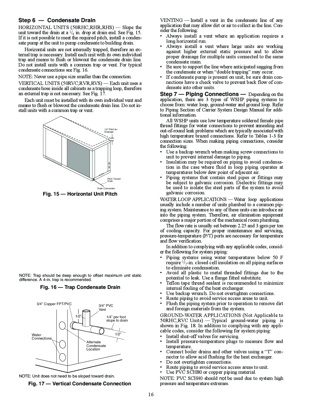
HORIZONTAL UNITS (50RHC,RHR,RHS) — Slope the unit toward the drain at a 1/4 in. drop at drain end. See Fig. 15. If it is not possible to meet the required pitch, install a conden- sate pump at the unit to pump condensate to building drain.
Horizontal units are not internally trapped, therefore an ex- ternal trap is necessary. Install each unit with its own individual trap and means to flush or blowout the condensate drain line. Do not install units with a common trap or vent. For typical condensate connections see Fig. 16.
NOTE: Never use a pipe size smaller than the connection.
VERTICAL UNITS (50RVC,RVR,RVS) — Each unit uses a condensate hose inside all cabinets as a trapping loop, therefore an external trap is not necessary. See Fig. 17.
Each unit must be installed with its own individual vent and means to flush or blowout the condensate drain line. Do not in- stall units with a common trap or vent.
1/4” Pitch for Drainage
Pitch Toward
Drain
Drain Connection
Fig. 15 — Horizontal Unit Pitch
NOTE: Trap should be deep enough to offset maximum unit static difference. A
Fig. 16 — Trap Condensate Drain
3/4” Copper FPT/PVC | 3/4” PVC |
| |
| Vent |
1/2” | 1/4” per foot |
| slope to drain |
Water | 1/2” |
Connections | Alternate |
| |
| Condensate |
| Location |
NOTE: Unit does not need to be sloped toward drain.
Fig. 17 — Vertical Condensate Connection
VENTING — Install a vent in the condensate line of any application that may allow dirt or air to collect in the line. Con- sider the following:
•Always install a vent where an application requires a long horizontal run.
•Always install a vent where large units are working against higher external static pressure and to allow proper drainage for multiple units connected to the same condensate main.
•Be sure to support the line where anticipated sagging from the condensate or when “double trapping” may occur.
•If condensate pump is present on unit, be sure drain con- nections have a check valve to prevent back flow of con- densate into other units.
Step 7 — Piping Connections — Depending on the application, there are 3 types of WSHP piping systems to choose from: water loop,
All WSHP units use low temperature soldered female pipe thread fittings for water connections to prevent annealing and
•Use a backup wrench when making screw connections to unit to prevent internal damage to piping.
•Insulation may be required on piping to avoid condensa- tion in the case where fluid in loop piping operates at temperatures below dew point of adjacent air.
•Piping systems that contain steel pipes or fittings may be subject to galvanic corrosion. Dielectric fittings may be used to isolate the steel parts of the system to avoid galvanic corrosion.
WATER LOOP APPLICATIONS — Water loop applications usually include a number of units plumbed to a common pip- ing system. Maintenance to any of these units can introduce air into the piping system. Therefore, air elimination equipment comprises a major portion of the mechanical room plumbing.
The flow rate is usually set between 2.25 and 3 gpm per ton of cooling capacity. For proper maintenance and servicing,
In addition to complying with any applicable codes, consid- er the following for system piping:
•Piping systems using water temperatures below 50 F require
•Avoid all plastic to metal threaded fittings due to the potential to leak. Use a flange fitted substitute.
•Teflon tape thread sealant is recommended to minimize internal fouling of the heat exchanger.
•Use backup wrench. Do not overtighten connections.
•Route piping to avoid service access areas to unit.
•Flush the piping system prior to operation to remove dirt and foreign materials from the system.
•Install
•Install
•Connect boiler drains and other valves using a “T” con- nector to allow acid flushing for the heat exchanger.
•Do not overtighten connections.
•Route piping to avoid service access areas to unit.
•Use PVC SCH80 or copper piping material.
NOTE: PVC SCH40 should not be used due to system high pressure and temperature extremes.
16