Unit Start-Up Heating Mode
NOTE: Operate the unit in heating cycle after checking the cooling cycle. Allow 5 minutes between tests for the pressure or reversing valve to equalize.
1.Turn thermostat to lowest setting and set thermostat switch to HEAT position.
2.Slowly turn the thermostat to a higher temperature until the compressor activates.
3.Check for warm air delivery at the unit grille within a few minutes after the unit has begun to operate.
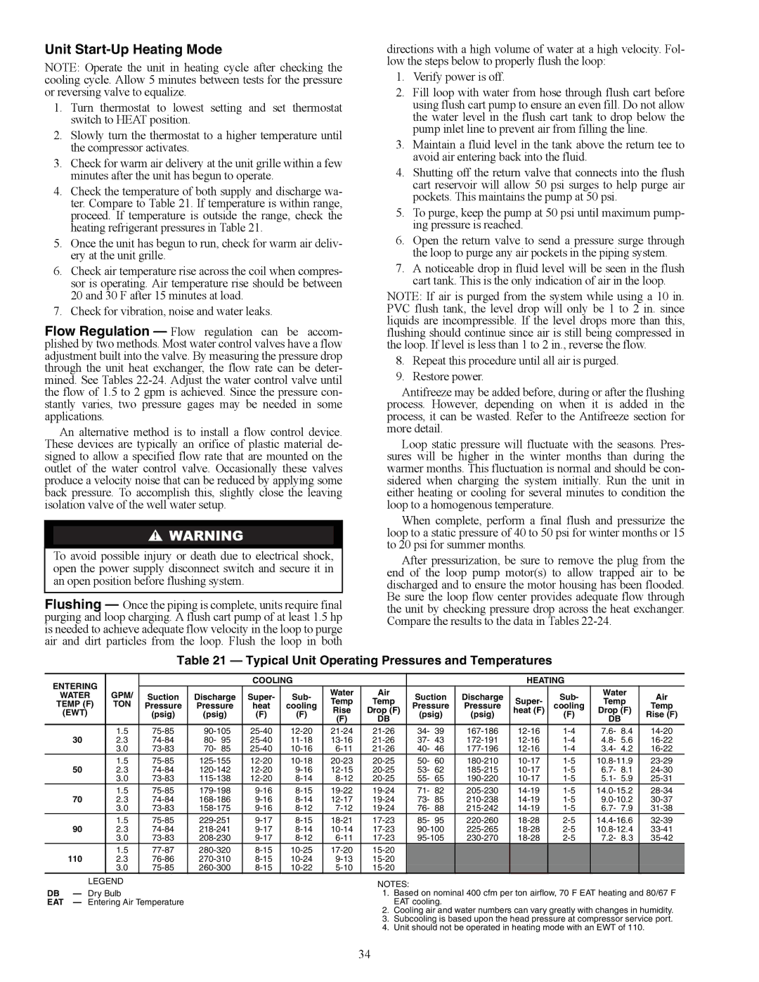
4.Check the temperature of both supply and discharge wa- ter. Compare to Table 21. If temperature is within range, proceed. If temperature is outside the range, check the heating refrigerant pressures in Table 21.
5.Once the unit has begun to run, check for warm air deliv- ery at the unit grille.
6.Check air temperature rise across the coil when compres- sor is operating. Air temperature rise should be between 20 and 30 F after 15 minutes at load.
7.Check for vibration, noise and water leaks.
Flow Regulation — Flow regulation can be accom- plished by two methods. Most water control valves have a flow adjustment built into the valve. By measuring the pressure drop through the unit heat exchanger, the flow rate can be deter- mined. See Tables
An alternative method is to install a flow control device. These devices are typically an orifice of plastic material de- signed to allow a specified flow rate that are mounted on the outlet of the water control valve. Occasionally these valves produce a velocity noise that can be reduced by applying some back pressure. To accomplish this, slightly close the leaving isolation valve of the well water setup.
To avoid possible injury or death due to electrical shock, open the power supply disconnect switch and secure it in an open position before flushing system.
Flushing — Once the piping is complete, units require final purging and loop charging. A flush cart pump of at least 1.5 hp is needed to achieve adequate flow velocity in the loop to purge air and dirt particles from the loop. Flush the loop in both
directions with a high volume of water at a high velocity. Fol- low the steps below to properly flush the loop:
1.Verify power is off.
2.Fill loop with water from hose through flush cart before using flush cart pump to ensure an even fill. Do not allow the water level in the flush cart tank to drop below the pump inlet line to prevent air from filling the line.
3.Maintain a fluid level in the tank above the return tee to avoid air entering back into the fluid.
4.Shutting off the return valve that connects into the flush cart reservoir will allow 50 psi surges to help purge air pockets. This maintains the pump at 50 psi.
5.To purge, keep the pump at 50 psi until maximum pump- ing pressure is reached.
6.Open the return valve to send a pressure surge through the loop to purge any air pockets in the piping system.
7.A noticeable drop in fluid level will be seen in the flush cart tank. This is the only indication of air in the loop.
NOTE: If air is purged from the system while using a 10 in. PVC flush tank, the level drop will only be 1 to 2 in. since liquids are incompressible. If the level drops more than this, flushing should continue since air is still being compressed in the loop. If level is less than 1 to 2 in., reverse the flow.
8.Repeat this procedure until all air is purged.
9.Restore power.
Antifreeze may be added before, during or after the flushing process. However, depending on when it is added in the process, it can be wasted. Refer to the Antifreeze section for more detail.
Loop static pressure will fluctuate with the seasons. Pres- sures will be higher in the winter months than during the warmer months. This fluctuation is normal and should be con- sidered when charging the system initially. Run the unit in either heating or cooling for several minutes to condition the loop to a homogenous temperature.
When complete, perform a final flush and pressurize the loop to a static pressure of 40 to 50 psi for winter months or 15 to 20 psi for summer months.
After pressurization, be sure to remove the plug from the end of the loop pump motor(s) to allow trapped air to be discharged and to ensure the motor housing has been flooded. Be sure the loop flow center provides adequate flow through the unit by checking pressure drop across the heat exchanger. Compare the results to the data in Tables
Table 21 — Typical Unit Operating Pressures and Temperatures
ENTERING |
|
|
|
| COOLING |
|
|
|
|
| HEATING |
|
|
| |||
WATER | GPM/ | Suction | Discharge | Super- | Sub- | Water | Air | Suction | Discharge |
| Sub- | Water | Air | ||||
Temp | Temp | Super- | Temp | ||||||||||||||
TEMP (F) | TON | Pressure | Pressure | heat | cooling | Pressure | Pressure | cooling | Temp | ||||||||
(EWT) |
| (psig) | (psig) | (F) | (F) | Rise | Drop (F) | (psig) | (psig) | heat (F) | (F) | Drop (F) | Rise (F) | ||||
|
|
|
|
|
|
| (F) | DB |
|
|
|
|
| DB |
|
| |
30 | 1.5 | 34- | 39 | 7.6- | 8.4 | ||||||||||||
2.3 | 80- | 95 | 37- | 43 | 4.8- | 5.6 | |||||||||||
| 3.0 | 70- | 85 | 40- | 46 | 3.4- | 4.2 | ||||||||||
50 | 1.5 | 50- 60 | |||||||||||||||
2.3 | 53- | 62 | 6.7- | 8.1 | |||||||||||||
| 3.0 | 55- | 65 | 5.1- | 5.9 | ||||||||||||
70 | 1.5 | 71- 82 | |||||||||||||||
2.3 | 73- | 85 | |||||||||||||||
| 3.0 | 76- | 88 | 6.7- | 7.9 | ||||||||||||
90 | 1.5 | 85- 95 | |||||||||||||||
2.3 | |||||||||||||||||
| 3.0 | 7.2- | 8.3 | ||||||||||||||
110 | 1.5 |
|
|
|
|
|
|
|
| ||||||||
2.3 |
|
|
|
|
|
|
|
| |||||||||
| 3.0 |
|
|
|
|
|
|
|
| ||||||||
LEGEND
DB — Dry Bulb
EAT — Entering Air Temperature
NOTES:
1.Based on nominal 400 cfm per ton airflow, 70 F EAT heating and 80/67 F EAT cooling.
2.Cooling air and water numbers can vary greatly with changes in humidity.
3.Subcooling is based upon the head pressure at compressor service port.
4.Unit should not be operated in heating mode with an EWT of 110.
34