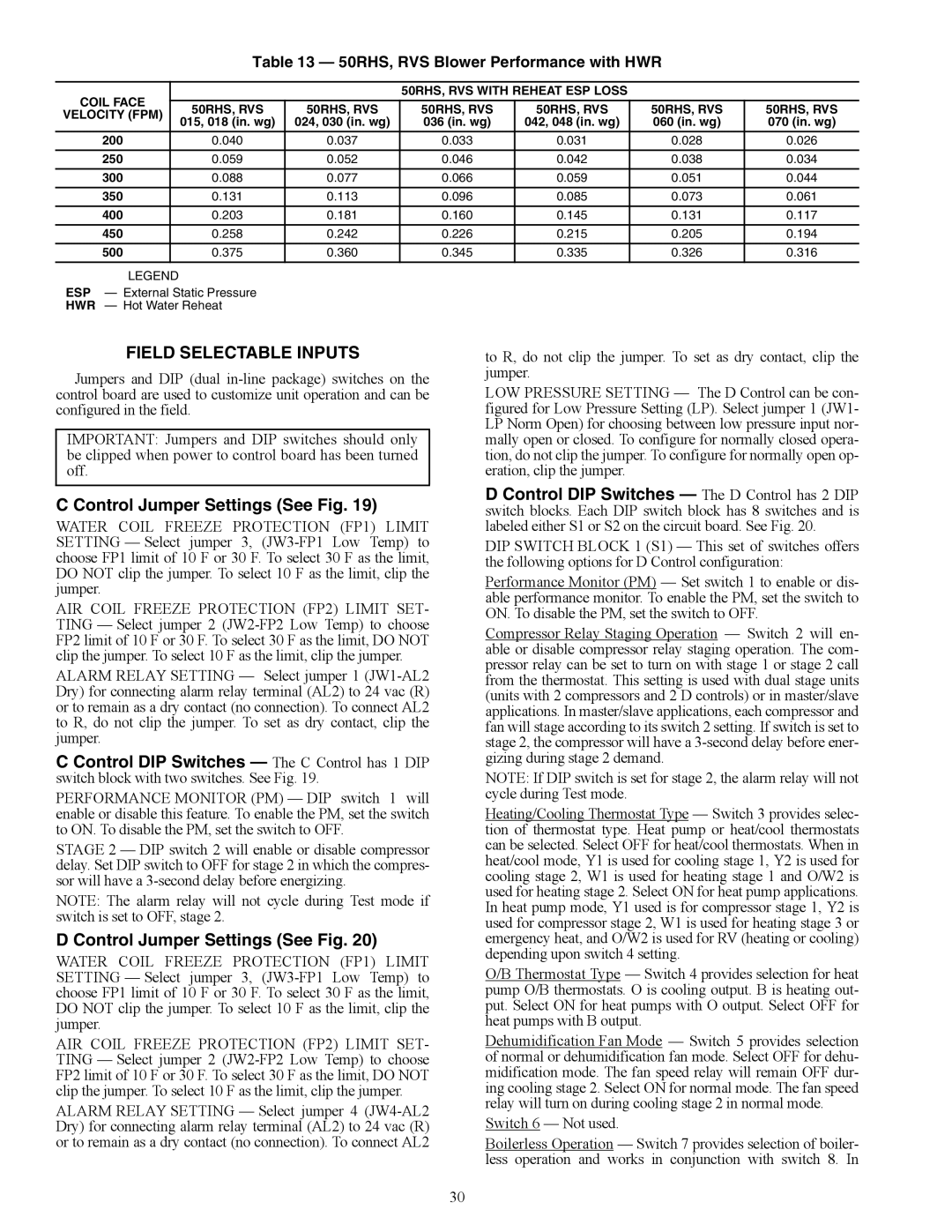
Table 13 — 50RHS, RVS Blower Performance with HWR
COIL FACE |
|
|
| 50RHS, RVS WITH REHEAT ESP LOSS |
|
| |
| 50RHS, RVS | 50RHS, RVS | 50RHS, RVS | 50RHS, RVS | 50RHS, RVS | 50RHS, RVS | |
VELOCITY (FPM) |
| ||||||
| 015, 018 (in. wg) | 024, 030 (in. wg) | 036 (in. wg) | 042, 048 (in. wg) | 060 (in. wg) | 070 (in. wg) | |
|
| ||||||
|
|
|
|
|
|
|
|
200 |
| 0.040 | 0.037 | 0.033 | 0.031 | 0.028 | 0.026 |
|
|
|
|
|
|
|
|
250 |
| 0.059 | 0.052 | 0.046 | 0.042 | 0.038 | 0.034 |
|
|
|
|
|
|
|
|
300 |
| 0.088 | 0.077 | 0.066 | 0.059 | 0.051 | 0.044 |
|
|
|
|
|
|
|
|
350 |
| 0.131 | 0.113 | 0.096 | 0.085 | 0.073 | 0.061 |
|
|
|
|
|
|
|
|
400 |
| 0.203 | 0.181 | 0.160 | 0.145 | 0.131 | 0.117 |
|
|
|
|
|
|
|
|
450 |
| 0.258 | 0.242 | 0.226 | 0.215 | 0.205 | 0.194 |
|
|
|
|
|
|
|
|
500 |
| 0.375 | 0.360 | 0.345 | 0.335 | 0.326 | 0.316 |
|
|
|
|
|
|
|
|
LEGEND |
|
|
|
|
|
| |
ESP — External Static Pressure
HWR — Hot Water Reheat
FIELD SELECTABLE INPUTS
Jumpers and DIP (dual
IMPORTANT: Jumpers and DIP switches should only be clipped when power to control board has been turned off.
C Control Jumper Settings (See Fig. 19)
WATER COIL FREEZE PROTECTION (FP1) LIMIT SETTING — Select jumper 3,
AIR COIL FREEZE PROTECTION (FP2) LIMIT SET- TING — Select jumper 2
ALARM RELAY SETTING — Select jumper 1
C Control DIP Switches — The C Control has 1 DIP switch block with two switches. See Fig. 19.
PERFORMANCE MONITOR (PM) — DIP switch 1 will enable or disable this feature. To enable the PM, set the switch to ON. To disable the PM, set the switch to OFF.
STAGE 2 — DIP switch 2 will enable or disable compressor delay. Set DIP switch to OFF for stage 2 in which the compres- sor will have a
NOTE: The alarm relay will not cycle during Test mode if switch is set to OFF, stage 2.
D Control Jumper Settings (See Fig. 20)
WATER COIL FREEZE PROTECTION (FP1) LIMIT SETTING — Select jumper 3,
AIR COIL FREEZE PROTECTION (FP2) LIMIT SET- TING — Select jumper 2
ALARM RELAY SETTING — Select jumper 4
to R, do not clip the jumper. To set as dry contact, clip the jumper.
LOW PRESSURE SETTING — The D Control can be con- figured for Low Pressure Setting (LP). Select jumper 1 (JW1- LP Norm Open) for choosing between low pressure input nor- mally open or closed. To configure for normally closed opera- tion, do not clip the jumper. To configure for normally open op- eration, clip the jumper.
D Control DIP Switches — The D Control has 2 DIP switch blocks. Each DIP switch block has 8 switches and is labeled either S1 or S2 on the circuit board. See Fig. 20.
DIP SWITCH BLOCK 1 (S1) — This set of switches offers the following options for D Control configuration:
Performance Monitor (PM) — Set switch 1 to enable or dis- able performance monitor. To enable the PM, set the switch to ON. To disable the PM, set the switch to OFF.
Compressor Relay Staging Operation — Switch 2 will en- able or disable compressor relay staging operation. The com- pressor relay can be set to turn on with stage 1 or stage 2 call from the thermostat. This setting is used with dual stage units (units with 2 compressors and 2 D controls) or in master/slave applications. In master/slave applications, each compressor and fan will stage according to its switch 2 setting. If switch is set to stage 2, the compressor will have a
NOTE: If DIP switch is set for stage 2, the alarm relay will not cycle during Test mode.
Heating/Cooling Thermostat Type — Switch 3 provides selec- tion of thermostat type. Heat pump or heat/cool thermostats can be selected. Select OFF for heat/cool thermostats. When in heat/cool mode, Y1 is used for cooling stage 1, Y2 is used for cooling stage 2, W1 is used for heating stage 1 and O/W2 is used for heating stage 2. Select ON for heat pump applications. In heat pump mode, Y1 used is for compressor stage 1, Y2 is used for compressor stage 2, W1 is used for heating stage 3 or emergency heat, and O/W2 is used for RV (heating or cooling) depending upon switch 4 setting.
O/B Thermostat Type — Switch 4 provides selection for heat pump O/B thermostats. O is cooling output. B is heating out- put. Select ON for heat pumps with O output. Select OFF for heat pumps with B output.
Dehumidification Fan Mode — Switch 5 provides selection of normal or dehumidification fan mode. Select OFF for dehu- midification mode. The fan speed relay will remain OFF dur- ing cooling stage 2. Select ON for normal mode. The fan speed relay will turn on during cooling stage 2 in normal mode.
Switch 6 — Not used.
Boilerless Operation — Switch 7 provides selection of boiler- less operation and works in conjunction with switch 8. In
30