a50-8153
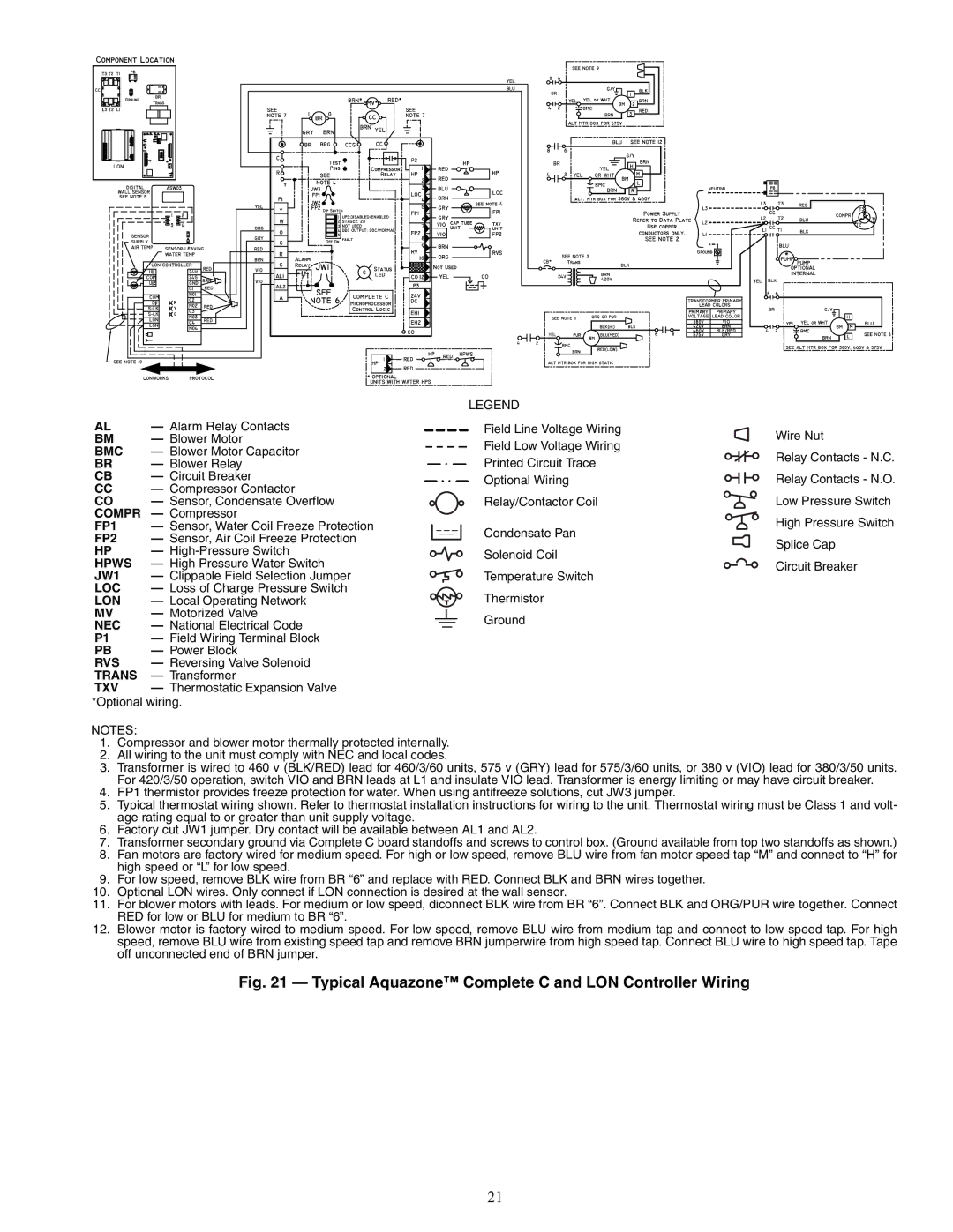
AL | — Alarm Relay Contacts |
BM | — Blower Motor |
BMC | — Blower Motor Capacitor |
BR | — Blower Relay |
CB | — Circuit Breaker |
CC— Compressor Contactor
CO | — Sensor, Condensate Overflow |
COMPR | — Compressor |
FP1 | — Sensor, Water Coil Freeze Protection |
FP2 | — Sensor, Air Coil Freeze Protection |
HP | — |
HPWS | — High Pressure Water Switch |
JW1 | — Clippable Field Selection Jumper |
LOC | — Loss of Charge Pressure Switch |
LON | — Local Operating Network |
MV | — Motorized Valve |
NEC | — National Electrical Code |
P1 | — Field Wiring Terminal Block |
PB | — Power Block |
RVS | — Reversing Valve Solenoid |
TRANS | — Transformer |
TXV | — Thermostatic Expansion Valve |
*Optional wiring.
LEGEND
Field Line Voltage Wiring
Field Low Voltage Wiring
Printed Circuit Trace
Optional Wiring
Relay/Contactor Coil
Condensate Pan
Solenoid Coil
Temperature Switch
Thermistor
Ground
Wire Nut
Relay Contacts - N.C.
Relay Contacts - N.O.
Low Pressure Switch
High Pressure Switch
Splice Cap
Circuit Breaker
NOTES:
1.Compressor and blower motor thermally protected internally.
2.All wiring to the unit must comply with NEC and local codes.
3.Transformer is wired to 460 v (BLK/RED) lead for 460/3/60 units, 575 v (GRY) lead for 575/3/60 units, or 380 v (VIO) lead for 380/3/50 units. For 420/3/50 operation, switch VIO and BRN leads at L1 and insulate VIO lead. Transformer is energy limiting or may have circuit breaker.
4.FP1 thermistor provides freeze protection for water. When using antifreeze solutions, cut JW3 jumper.
5.Typical thermostat wiring shown. Refer to thermostat installation instructions for wiring to the unit. Thermostat wiring must be Class 1 and volt- age rating equal to or greater than unit supply voltage.
6.Factory cut JW1 jumper. Dry contact will be available between AL1 and AL2.
7.Transformer secondary ground via Complete C board standoffs and screws to control box. (Ground available from top two standoffs as shown.)
8.Fan motors are factory wired for medium speed. For high or low speed, remove BLU wire from fan motor speed tap “M” and connect to “H” for high speed or “L” for low speed.
9.For low speed, remove BLK wire from BR “6” and replace with RED. Connect BLK and BRN wires together.
10.Optional LON wires. Only connect if LON connection is desired at the wall sensor.
11.For blower motors with leads. For medium or low speed, diconnect BLK wire from BR “6”. Connect BLK and ORG/PUR wire together. Connect RED for low or BLU for medium to BR “6”.
12.Blower motor is factory wired to medium speed. For low speed, remove BLU wire from medium tap and connect to low speed tap. For high speed, remove BLU wire from existing speed tap and remove BRN jumperwire from high speed tap. Connect BLU wire to high speed tap. Tape off unconnected end of BRN jumper.
Fig. 21 — Typical Aquazone™ Complete C and LON Controller Wiring
21