Water
Connection End
Return Air
Supply
Duct
Side Discharge | Water |
| Connection End |
Return Air![]()
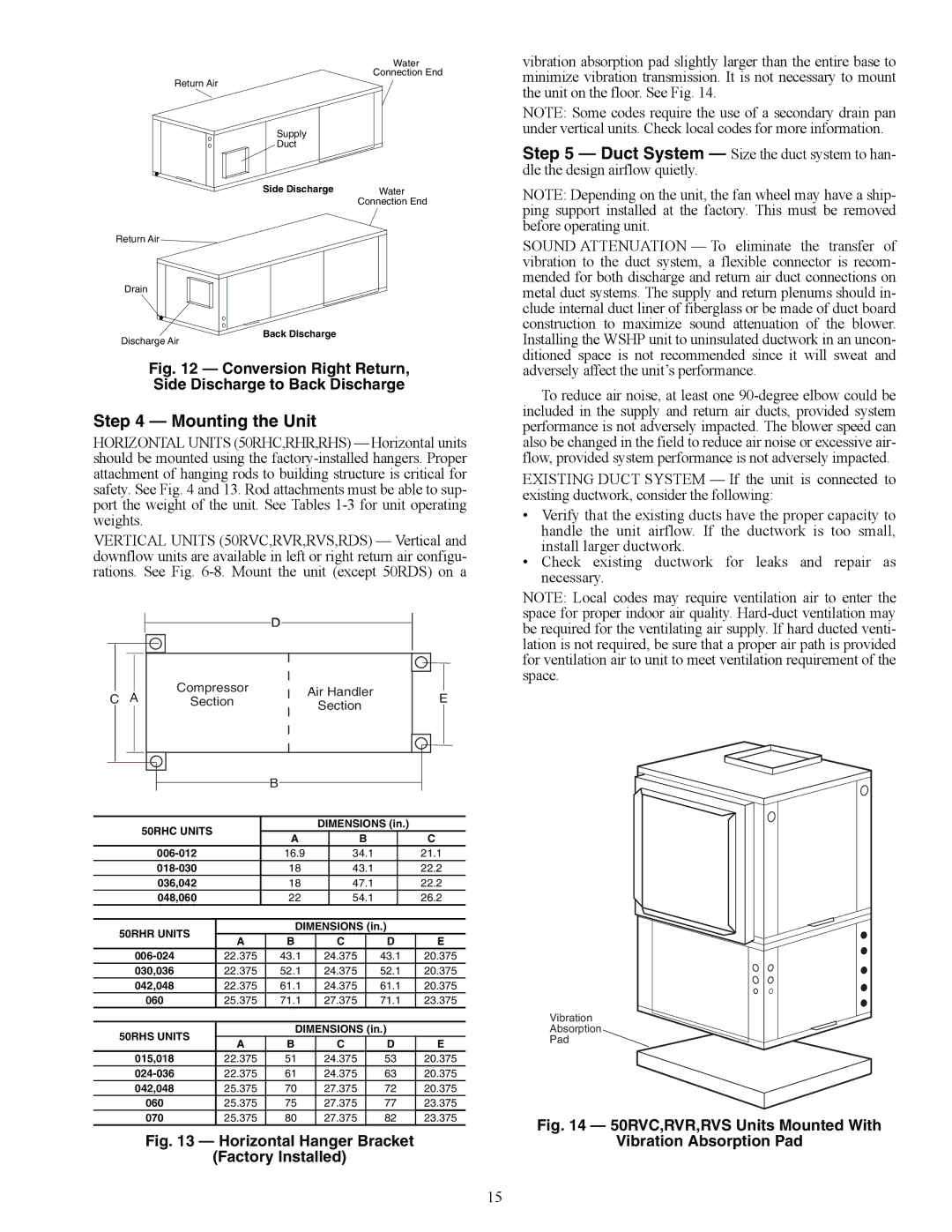
vibration absorption pad slightly larger than the entire base to minimize vibration transmission. It is not necessary to mount the unit on the floor. See Fig. 14.
NOTE: Some codes require the use of a secondary drain pan under vertical units. Check local codes for more information.
Step 5 — Duct System — Size the duct system to han- dle the design airflow quietly.
NOTE: Depending on the unit, the fan wheel may have a ship- ping support installed at the factory. This must be removed before operating unit.
SOUND ATTENUATION — To eliminate the transfer of vibration to the duct system, a flexible connector is recom- mended for both discharge and return air duct connections on
Drain
Discharge Air
Back Discharge
metal duct systems. The supply and return plenums should in- clude internal duct liner of fiberglass or be made of duct board construction to maximize sound attenuation of the blower. Installing the WSHP unit to uninsulated ductwork in an uncon- ditioned space is not recommended since it will sweat and
Fig. 12 — Conversion Right Return,
Side Discharge to Back Discharge
Step 4 — Mounting the Unit
HORIZONTAL UNITS (50RHC,RHR,RHS) — Horizontal units should be mounted using the
VERTICAL UNITS (50RVC,RVR,RVS,RDS) — Vertical and downflow units are available in left or right return air configu- rations. See Fig.
![]() D
D
|
|
|
|
|
|
|
|
|
|
|
|
|
|
|
|
|
|
|
|
|
|
|
|
|
|
|
| Compressor |
|
|
|
|
|
|
|
|
|
| Air Handler |
|
|
| |
C |
| A |
|
|
|
| E | |||
|
|
| Section |
|
| |||||
|
|
| Section |
|
| |||||
|
|
|
|
|
|
|
|
|
| |
|
|
|
|
|
|
|
|
|
|
|
|
|
|
|
|
|
|
|
|
|
|
|
|
|
|
|
|
|
|
|
|
|
|
|
|
|
|
|
|
|
|
|
|
B
50RHC UNITS |
| DIMENSIONS (in.) |
| ||
A |
| B |
| C | |
|
|
| |||
16.9 |
| 34.1 |
| 21.1 | |
18 |
| 43.1 |
| 22.2 | |
036,042 | 18 |
| 47.1 |
| 22.2 |
048,060 | 22 |
| 54.1 |
| 26.2 |
50RHR UNITS |
| DIMENSIONS (in.) |
| |||
A | B | C | D | E | ||
| ||||||
22.375 | 43.1 | 24.375 | 43.1 | 20.375 | ||
030,036 | 22.375 | 52.1 | 24.375 | 52.1 | 20.375 | |
042,048 | 22.375 | 61.1 | 24.375 | 61.1 | 20.375 | |
060 | 25.375 | 71.1 | 27.375 | 71.1 | 23.375 | |
50RHS UNITS |
| DIMENSIONS (in.) |
| |||
A | B | C | D | E | ||
| ||||||
015,018 | 22.375 | 51 | 24.375 | 53 | 20.375 | |
22.375 | 61 | 24.375 | 63 | 20.375 | ||
042,048 | 25.375 | 70 | 27.375 | 72 | 20.375 | |
060 | 25.375 | 75 | 27.375 | 77 | 23.375 | |
070 | 25.375 | 80 | 27.375 | 82 | 23.375 | |
Fig. 13 — Horizontal Hanger Bracket
(Factory Installed)
adversely affect the unit’s performance.
To reduce air noise, at least one
EXISTING DUCT SYSTEM — If the unit is connected to existing ductwork, consider the following:
•Verify that the existing ducts have the proper capacity to handle the unit airflow. If the ductwork is too small, install larger ductwork.
•Check existing ductwork for leaks and repair as necessary.
NOTE: Local codes may require ventilation air to enter the space for proper indoor air quality.
Vibration
Absorption
Pad
Fig. 14 — 50RVC,RVR,RVS Units Mounted With
Vibration Absorption Pad
15