Chapter 2 Switch Installation
Installing the Cable Guard (Optional)
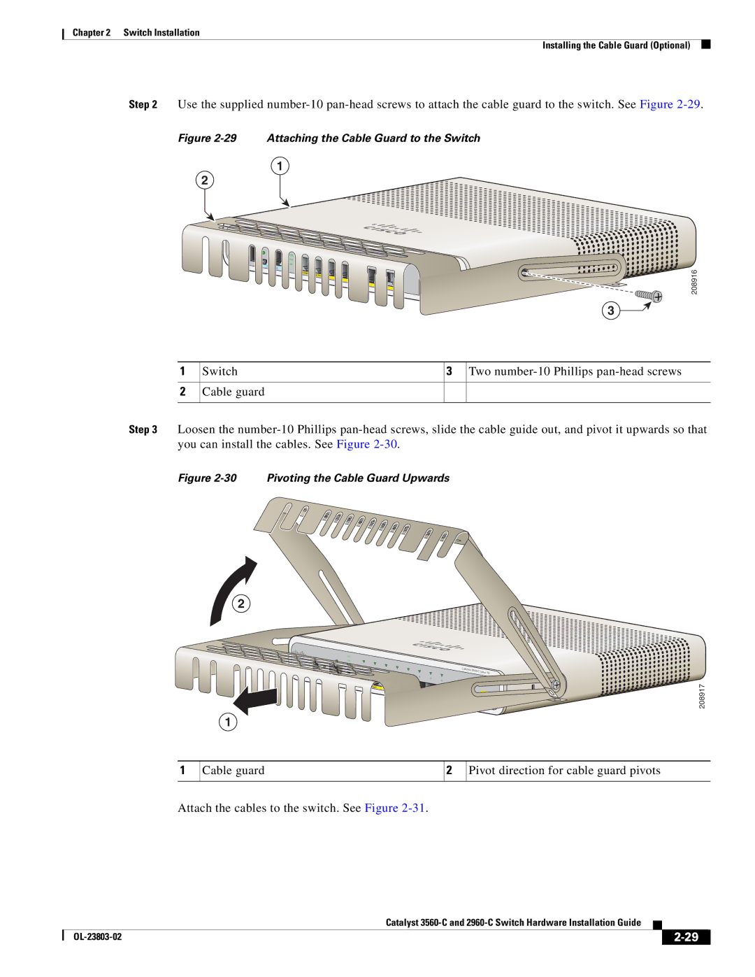
Step 2 Use the supplied
Figure 2-29 Attaching the Cable Guard to the Switch
1
2
MODE
CONSOLE
SYST STAT DPLX SPD PoE PD
1 |
|
|
|
|
|
|
|
|
|
|
|
| 2 | 3 |
|
|
|
|
| Catalyst |
| ||
|
|
|
|
|
|
|
|
| |||
|
|
|
| 4 | 5 |
|
|
|
| Series | |
|
|
|
|
| 6 | 7 |
|
|
| ||
|
|
|
|
|
|
|
|
| |||
|
|
|
|
|
|
|
|
|
| ||
|
|
|
|
|
|
| 8 |
|
|
| |
|
|
|
|
|
|
|
|
|
|
| |
|
|
|
|
|
|
|
|
|
|
|
|
POWER |
|
|
|
|
|
|
|
|
|
|
|
| OVER | E |
|
|
|
|
|
|
|
|
|
|
| THERNET |
|
|
|
|
| 1 |
| 2 | |
|
|
|
|
|
|
|
|
| |||
|
|
|
|
|
|
|
|
|
|
| |
PD
208916
3 ![]()
1
2
Switch
Cable guard
3
Two
Step 3 Loosen the
Figure 2-30 Pivoting the Cable Guard Upwards
2
| SYST |
|
|
|
|
|
|
|
|
|
|
|
| STAT |
|
|
|
|
|
|
|
|
|
|
|
| 1 |
|
|
|
|
|
|
|
|
|
|
|
|
| 2 | 3 |
|
|
|
|
| Catalyst |
|
| |
|
|
| 4 | 5 |
|
|
|
| Series | PD | ||
| PD |
|
|
| 6 |
|
|
|
|
| ||
CONSOLE |
|
|
|
| 7 |
|
|
|
|
| ||
|
|
|
|
|
| 8 |
|
|
|
| ||
|
|
|
|
|
|
|
|
|
|
| ||
|
|
|
|
|
|
|
| 1 |
| 2 | ||
|
|
|
|
|
|
|
|
|
|
| ||
1
208917
1
Cable guard
2
Pivot direction for cable guard pivots
Attach the cables to the switch. See Figure
|
| Catalyst |
|
| |
|
|
| |||
|
|
|
| ||
|
|
|
| ||
