Chapter 2 Switch Installation
Installing the Cable Guard (Optional)
Installing the Cable Guard (Optional)
The cable guard prevents tampering with the cables after the cables are installed. The cable guard
Note You can use the cable guard when the switch is mounted on a desk, under a desk, or on a wall.
The cable guard is shipped with these items:
•Two 0.5 in. (12.7 mm)
•Two
•Two washers
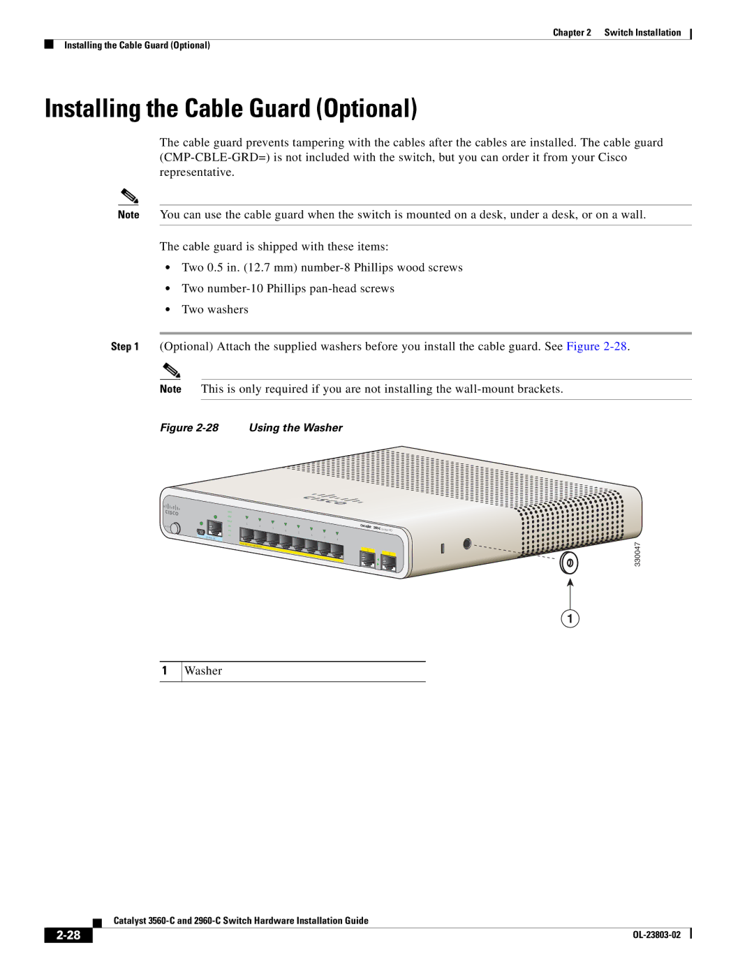
Step 1 (Optional) Attach the supplied washers before you install the cable guard. See Figure
Note This is only required if you are not installing the
Figure 2-28 Using the Washer
|
| SYST |
|
|
|
|
|
|
|
|
|
| STAT |
|
|
|
|
|
|
|
|
|
| DPLX | 1 |
|
|
|
|
|
| |
M ODE |
| SPD | 2 |
|
|
|
|
| ||
|
| 3 |
|
| Series | PD | ||||
|
|
|
|
| ||||||
|
| PoE | 4 | 5 |
| |||||
|
|
|
| |||||||
|
| PD |
|
|
|
| 6 |
|
|
|
|
| CONSOLE |
|
|
|
| 8 |
|
|
|
|
|
|
|
|
|
| 7 |
|
|
|
|
|
| POW |
|
|
|
|
|
|
|
|
|
| ER | OVER | E |
|
|
|
|
|
|
|
|
|
|
|
|
| |||
|
|
|
|
| THERNET |
| 1 |
|
| |
|
|
|
|
|
|
|
|
| ||
|
|
|
|
|
|
| 2 | |||
330047
1
1
Washer
| Catalyst |