Chapter 1 Product Overview
Front Panel
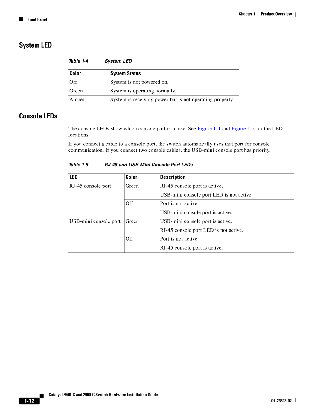
System LED
Table | System LED | |
|
|
|
Color |
| System Status |
|
|
|
Off |
| System is not powered on. |
|
|
|
Green |
| System is operating normally. |
|
|
|
Amber |
| System is receiving power but is not operating properly. |
|
|
|
Console LEDs
The console LEDs show which console port is in use. See Figure
If you connect a cable to a console port, the switch automatically uses that port for console communication. If you connect two console cables, the
Table | |||
|
|
|
|
LED |
| Color | Description |
|
|
| |
Green | |||
|
|
| |
|
|
|
|
|
| Off | Port is not active. |
|
|
| |
|
|
| |
Green | |||
|
|
| |
|
|
|
|
|
| Off | Port is not active. |
|
|
| |
|
|
|
|
| Catalyst |