Chapter 2 Switch Installation
Removing SFP Modules
Warning Class 1 laser product. Statement 1008
Step 1 Attach an
Step 2 Find the send (TX) and receive (RX) markings on the module top.
On some SFP modules, the TX and RX markings might be replaced by arrows that show the direction of the connection, either send or receive.
Step 3 If the module has a
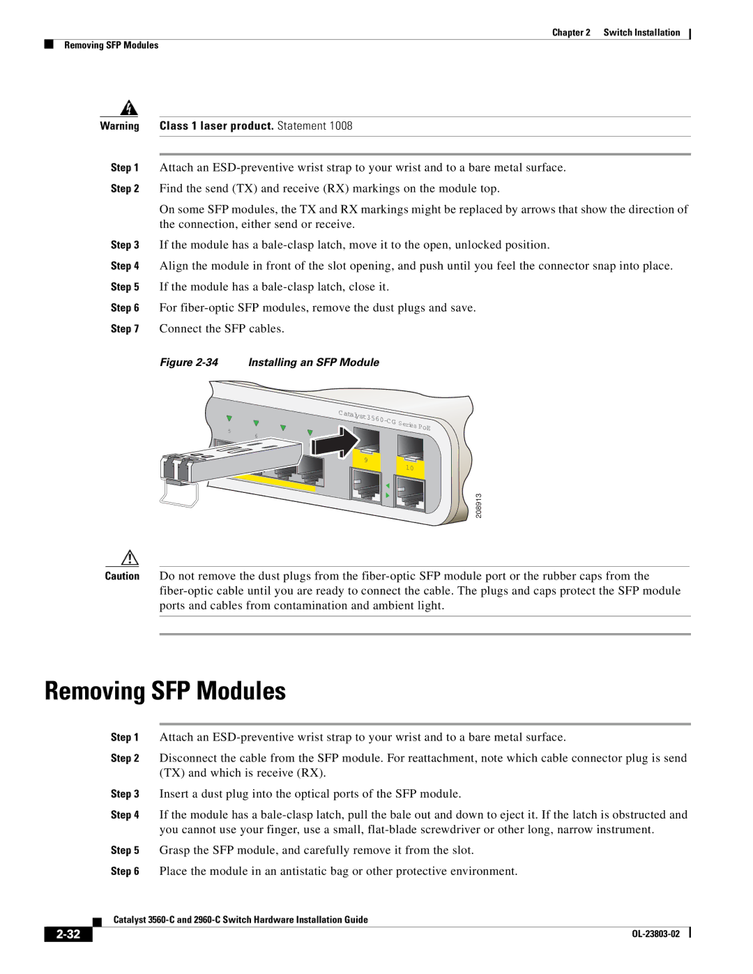
Step 4 Align the module in front of the slot opening, and push until you feel the connector snap into place. Step 5 If the module has a
Step 6 For
Step 7 Connect the SFP cables.
Figure 2-34 Installing an SFP Module
5
| Catal |
|
|
|
| yst3560- |
|
|
|
6 | C G | Series |
| PoE |
|
| |||
|
|
| ||
|
|
|
| |
8 |
|
|
|
|
9 |
|
|
| |
10 |
|
| ||
208913
Caution Do not remove the dust plugs from the
Removing SFP Modules
|
|
| Step 1 | Attach an | |
|
|
| Step 2 | Disconnect the cable from the SFP module. For reattachment, note which cable connector plug is send | |
|
|
|
| (TX) and which is receive (RX). | |
|
|
| Step 3 | Insert a dust plug into the optical ports of the SFP module. | |
|
|
| Step 4 | If the module has a | |
|
|
|
| you cannot use your finger, use a small, | |
|
|
| Step 5 | Grasp the SFP module, and carefully remove it from the slot. | |
|
|
| Step 6 | Place the module in an antistatic bag or other protective environment. | |
|
|
| Catalyst | ||
|
|
| |||
|
|
|
|
|
|
|
|
|
|
| |
|
|
|
| ||
