Chapter 2 Switch Installation
Mounting the Switch
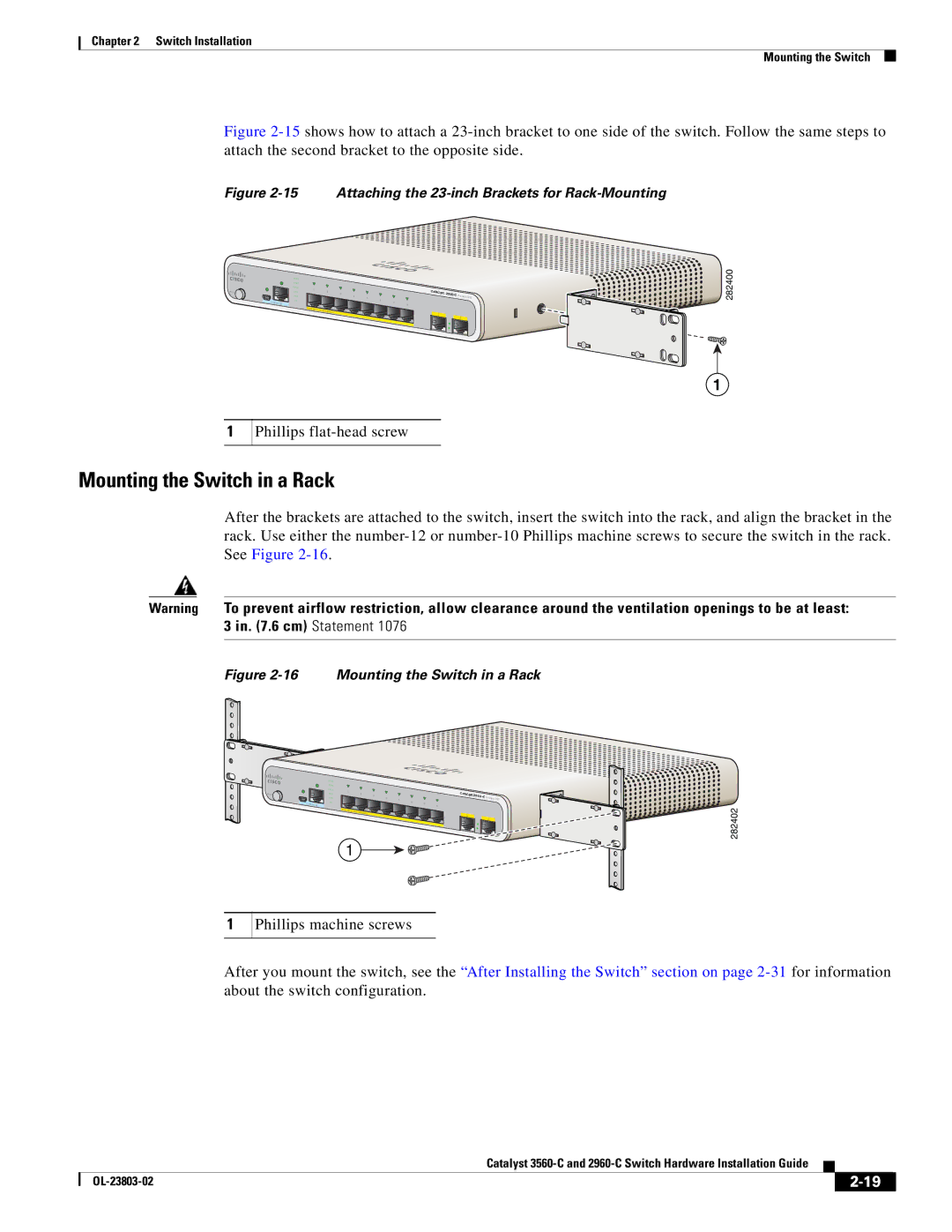
Figure 2-15 shows how to attach a 23-inch bracket to one side of the switch. Follow the same steps to attach the second bracket to the opposite side.
Figure 2-15 Attaching the 23-inch Brackets for Rack-Mounting
M O D E
CO NSO LE
SYST
STAT
DPLX SPD PoE
PD
PO W
1 |
|
|
|
|
|
|
2 |
|
|
|
| ||
3 |
|
| Series | |||
5 |
|
| ||||
4 | 6 |
|
| |||
|
|
|
|
|
| |
|
|
|
| 7 |
|
|
|
|
|
| 8 |
|
|
ER |
|
|
|
|
|
|
O VER |
|
|
| |||
|
| ETH ERN ET |
| 1 |
| |
|
|
|
|
| ||
|
|
|
| 2 | ||
PD
282400
1
1
Phillips flat-head screw
Mounting the Switch in a Rack
After the brackets are attached to the switch, insert the switch into the rack, and align the bracket in the rack. Use either the
Warning To prevent airflow restriction, allow clearance around the ventilation openings to be at least: 3 in. (7.6 cm) Statement 1076
Figure 2-16 Mounting the Switch in a Rack
M O D E
| SYST |
|
|
|
|
|
|
|
|
| STAT |
|
|
|
|
|
|
|
|
| DPLX | 1 |
|
|
|
|
|
|
|
| SPD | 2 |
|
|
|
|
| ||
|
| 3 |
|
| Series | PD | |||
|
| 5 |
|
| |||||
| PoE | 4 | 6 |
|
|
| |||
CO | PD |
|
|
|
|
|
|
| |
NSO LE |
|
|
|
| 7 |
|
|
| |
|
|
|
|
| 8 |
|
|
| |
|
| PO W ER |
|
|
|
|
|
|
|
|
| O VER | ETH ERN ET |
| 1 |
|
| ||
|
|
|
|
| |||||
|
|
|
|
|
|
| |||
|
|
|
|
|
|
|
| ||
|
|
|
|
|
| 2 |
| ||
1
282402
1
Phillips machine screws
After you mount the switch, see the “After Installing the Switch” section on page
|
| Catalyst |
|
| |
|
|
| |||
|
|
|
| ||
|
|
|
| ||