Cisco Unified IP Phone 7906G and 7911G
Page
Copyright 2006 Cisco Systems, Inc. All rights reserved
Page
N T E N T S
Security Restrictions
Safety
Vii
Configuring Features, Templates, Services, and Users
Viii
PNG File Requirements for Custom Background Images
Symptom The Cisco Unified IP Phone Does Not Register with
Supporting International Users B-1
Xii
Overview
Audience
Xiii
Organization
Xiv
Appendix C, Technical Specifications
Cisco Unified CallManager Administration
Related Documentation
Appendix B, Supporting International Users
Obtaining Documentation
Cisco.com
Xvi
Documentation Feedback
Product Documentation DVD Ordering Documentation
Xvii
Cisco Product Security Overview
Xviii
Reporting Security Problems in Cisco Products
For Emergencies only security-alert@cisco.com
Xix
Obtaining Technical Assistance
Cisco Technical Support & Documentation Website
Submitting a Service Request
Definitions of Service Request Severity
Xxi
Obtaining Additional Publications and Information
Xxii
Xxiii
Document Conventions
Convention Description
Xxiv
Waarschuwing Belangrijke Veiligheidsinstructies
Varoitus Tärkeitä Turvallisuusohjeita
Xxv
Warnung Wichtige Sicherheitshinweise
Avvertenza Importanti Istruzioni Sulla Sicurezza
Xxvi
Aviso Instruções Importantes DE Segurança
Xxvii
Varning! Viktiga Säkerhetsanvisningar
Xxviii
Xxix
GEM Disse Anvisninger
Xxx
Xxxi
Xxxii
An Overview Cisco Unified IP Phone
Understanding the Cisco Unified IP Phones 7906G and 7911G
Cisco Unified IP Phones 7906G and 7911G
What Networking Protocols Are Used?
Networking Protocol Purpose Usage Notes
Dhcp
Srtp
What Features are Supported?
UDP
Related Topics
Feature Overview
Configuring Telephony Features
Telephony Features Available for the Phone,
Related Topic
Understanding Security Features for Cisco Unified IP Phones
Providing Users with Feature Information
Topic Reference
Overview of Supported Security Features
See the Troubleshooting Cisco Unified IP
See the Resetting or Restoring
Phone Security section on
Feature Description
Configuring Security on the Cisco Unified IP Phone
Section on page 3-17 for more information
Capf
Identifying Encrypted and Authenticated Phone Calls
Device Configuration Menu section on
Garp
Security Restrictions
Cisco Unified CallManager Database section on
OL-10008-01
Task Purpose For More Information
Phone Configuration window CallManager database
See the Configuring
See the Setting Up
Services section on
Softkey Templates
Installing Cisco Unified IP Phones
See the Adding Users to
Cisco Unified CallManag
Er section on
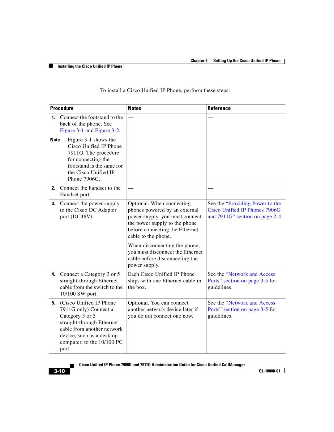
See the Providing Power
See the Installing
Cisco Unified IP Phones
7906G and 7911G
Startup Network Settings
Configuration Menu
Security on
See Appendix a
Providing Information to
Users
OL-10008-01
Preparing to Install Cisco Unified IP Phone on Your Network
OL-10008-01
Vlan
Providing Power to Cisco Unified IP Phones 7906G and 7911G
Power Outage
Power Guidelines
Obtaining Additional Information about Power
Power Type Guidelines
Understanding Phone Configuration Files
URL
Understanding the Phone Startup Process
Step Description Related Topics
Vlan
Cisco Unified CallMan
Phone Configuration
See the Understanding
Adding Phones to the Cisco Unified CallManager Database
Requires MAC Method Address?
Adding Phones with Auto-Registration
Adding Phones with Auto-Registration and Taps
Adding Phones with Cisco Unified CallManager Administration
MAC Address of a Cisco Unified IP Phone section on
Determining the MAC Address of a Cisco Unified IP Phone
Adding Phones with BAT
OL-10008-01
Setting Up the Cisco Unified IP Phone
Before You Begin
Handset, Speaker, Installing the Cisco Unified IP Phone,
Network Requirements
Cisco Unified CallManager Configuration
Safety
Setting Up the Cisco Unified IP Phone Before You Begin
Network and Access Ports
Network and Access Ports, Handset, Speaker, Headset,
Handset
Monitor Mode
Speaker
Headset
Activating Group Listen on the Phone
Audio Quality Subjective to User
Installing the Cisco Unified IP Phone
Connecting a Headset
Procedure Reference
154887
154389
Cisco Unified IP Phone Model 7906G Cable Connections
Cisco Unified IP Phone Model 7911G Cable Connections
Procedure
Mounting the Phone to a Wall
Before You Begin
Configuring Startup Network Settings
Verifying the Phone Startup Process
Configuring Security on the Cisco Unified IP Phone
Settings on the Cisco Unified IP Phone
Cisco Unified CallManager Administration Guide
Related Topic
OL-10008-01
Configuring Settings on Cisco Unified IP Phone
Displaying a Configuration Menu
Unlocking and Locking Options
Editing the Values of an Option Setting
Overview of Options Configurable from a Phone
Network Configuration Menu
Category Description Option
Network Configuration Menu
Option Description To Change
Option Description To Change
CTL File Screen section on
To the CTL File Screen section
Vlan ID
Option Description To Change
Option Description To Change
PC Vlan
Device Configuration Menu
CallManager Configuration Menu
State
Designation Description
Srst
Tftp
Http Configuration Menu
URL
Locale Configuration Menu
UI Configuration Menu
Media Configuration Menu
Ethernet Configuration Menu
Security Configuration Menu
10 Security Configuration Menu Options
QoS Configuration Menu
Displaying a Configuration Menu, Network Configuration Menu,
Network Configuration
Configuring Features, Templates Services, and Users
Telephony Features Available for the Phone
Feature Description Configuration Reference
System Guide, Understanding
Administration Guide, Feature
Call
CMC
FAC
System Guide, Call Pickup
Administration Guide , Meet-Me
Mcid
System Guide, Voice Mail
Mlpp
Button Templates section on
QRT
Administration Guide, Time
See the Configuring Softkey
Templates section on
Configuring Corporate Directories
Configuring Personal Directory
Configuring Softkey Templates
Modifying Phone Button Templates
Setting Up Services
Adding Users to Cisco Unified CallManager
Specifying Options that Appear on the User Options Web Pages
OL-10008-01
Customizing Cisco Unified IP Phone
Creating Custom Phone Rings
RingList.xml File Format Requirements
Ring CiscoIPPhoneRingList
Configuring a Custom Phone Ring
PCM File Requirements for Custom Ring Types
Creating Custom Background Images
List.xml File Format Requirements
List.xml Example
Configuring a Custom Background Image
PNG File Requirements for Custom Background Images
OL-10008-01
OL-10008-01
A P T E R
Security Configuration Menu
CTL File Screen
CTL File Information
Trust List Screen
Model Information Screen
Status Menu
CTL
MIC
LSC
Status Messages Screen
Press the Applications Menu button
Status
CallManager Administration section on
Network Configuration Menu section
Message Description Possible Explanation and Action
Adding Phones with Cisco Unified
Configuration Menu section on
Address
Address. See the Network Configuration
Menu section on page 4-7 section for
Network Configuration Menu section on
Phone. See the Firmware Versions Screen
Section on page 7-19 to verify the phone
See the Network Configuration Menu
Section on page 4-7 section for details
On page 4-7for details on assigning a
Network Statistics Screen
Select Network Statistics
PC port is in a link up state and has auto-negotiated
Firmware Versions Screen
OL-10008-01
Monitoring the Cisco Unified IP Phone Remotely
Accessing the Web Page for a Phone
Device Logs, Streaming Statistics,
Disabling Web Page Access
Device Information
Monitoring the Cisco Unified IP Phone Remotely
UDI
Network Configuration
Description
Description
Description
Description
Network Statistics
Ethernet Information Area Items
OL-10008-01
Device Logs
Streaming Statistics
Streaming Statistics
OL-10008-01
Troubleshooting and Maintenance
Resolving Startup Problems
Troubleshooting and Maintenance Resolving Startup Problems
Identifying Error Messages
Verifying Tftp Server Settings
Verifying DNS Settings
Creating a New Configuration File
Cisco Unified IP Phone Resets Unexpectedly
Verifying Dhcp Settings
Verifying Physical Connection
Identifying Intermittent Network Outages
Checking Static IP Address Settings
Verifying Voice Vlan Configuration
Eliminating DNS or Other Connectivity Errors
General Troubleshooting Tips
Problem Possible Cause
Summary Explanation
Unlocking and Locking Options section on page 4-3 for
Halfduxcollisionexceedthreshold
Performing a Basic Reset
Performing a Basic Reset, Performing a Factory Reset,
Operation Performing Explanation
Performing a Factory Reset
Locking Options section on
Unlocking and Locking Options
Section on page 4-3 . The press
Using the Quality Report Tool
Cleaning the Cisco Unified IP Phone
Where to Go for More Troubleshooting Information
Providing Information to Users
How Users Obtain Support for the Cisco Unified IP Phone
How Users Subscribe to Services and Configure Phone Features
How Users Get Copies of Cisco Unified IP Phone Manuals
How Users Access a Voice Messaging System
Cisco Unified CallManager section on
How Users Configure Personal Directory Entries
Supporting International Users
Appendix B Supporting International Users
Technical Specifications
Specification Value or Range
Cable Specifications
Network and Access Port Pinouts
Network Port Connector
Pin Number Function
Access Port Connector
RD+
OL-10008-01
Numerics
IN-1
IN-2
IN-3
IN-4
IN-5
IN-6
IN-7
IN-8
IN-9
IN-10
IN-11
Wall mounting Web Access Enabled 4-22web
IN-12
Page
USA