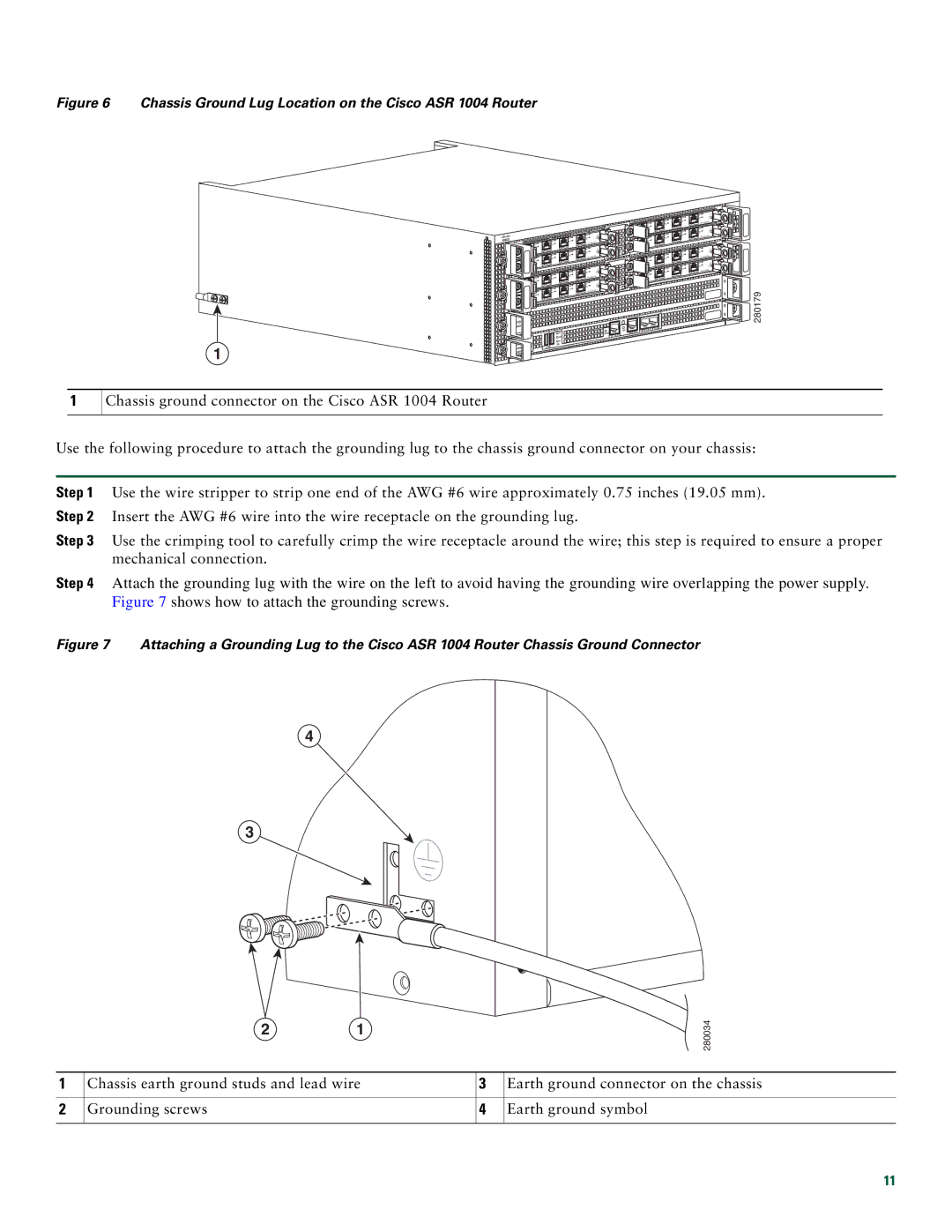
Figure 6 Chassis Ground Lug Location on the Cisco ASR 1004 Router
1
1
Chassis ground connector on the Cisco ASR 1004 Router
| |
| 3 |
| 2 |
| 1 |
| 0 |
| |
| 3 |
2 | |
3 | 1 |
2 | 0 |
1 |
|
0 | |
3 | 3 |
2 | 2 |
1 | 1 |
0 | 0 |
| |
| 3 |
2 | |
3 | 1 |
2 | 0 |
1 |
|
0 |
|
| |
3 |
|
2 |
|
1 |
|
0 |
|
|
|
|
|
|
| LINK | AUX |
|
|
|
|
|
| CON | |
|
|
|
| HD | CARRIER | BITS | MGMT ETHERNET |
|
|
|
| USB |
| ||
|
| CRIT |
|
|
|
| |
PWR | ACTV | MAJ |
| DF |
|
|
|
|
| DISK |
|
|
| ||
STAT | STBY | MIN | 0 | 1 |
|
|
|
|
|
|
|
|
| ||
280179
Use the following procedure to attach the grounding lug to the chassis ground connector on your chassis:
Step 1 Use the wire stripper to strip one end of the AWG #6 wire approximately 0.75 inches (19.05 mm). Step 2 Insert the AWG #6 wire into the wire receptacle on the grounding lug.
Step 3 Use the crimping tool to carefully crimp the wire receptacle around the wire; this step is required to ensure a proper mechanical connection.
Step 4 Attach the grounding lug with the wire on the left to avoid having the grounding wire overlapping the power supply. Figure 7 shows how to attach the grounding screws.
Figure 7 Attaching a Grounding Lug to the Cisco ASR 1004 Router Chassis Ground Connector
4
3
2 1
![]() 280034
280034
1 | Chassis earth ground studs and lead wire | 3 | Earth ground connector on the chassis |
|
|
|
|
2 | Grounding screws | 4 | Earth ground symbol |
|
|
|
|
11