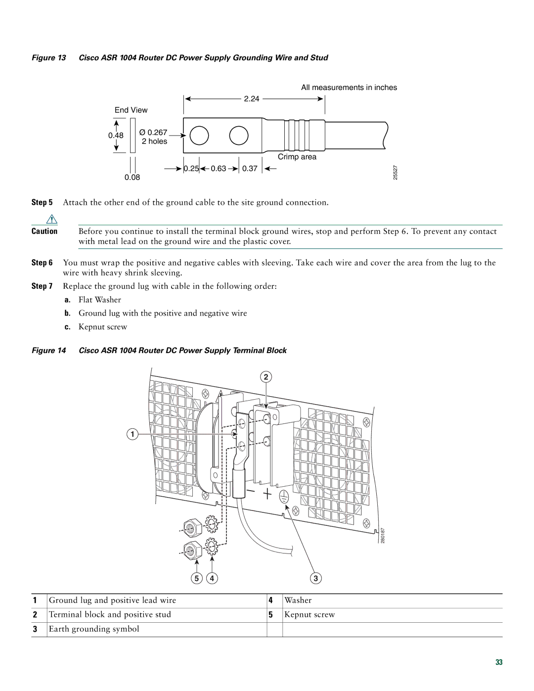
Figure 13 Cisco ASR 1004 Router DC Power Supply Grounding Wire and Stud
End View
All measurements in inches
2.24
0.48
Ø0.267
2 holes
| 0.25 |
|
| 0.63 |
|
|
| 0.37 |
|
|
| Crimp area |
|
|
|
|
|
| |||||||
|
|
|
|
|
|
|
|
|
| |||
|
|
|
0.08
Step 5 Attach the other end of the ground cable to the site ground connection.
25527
Caution Before you continue to install the terminal block ground wires, stop and perform Step 6. To prevent any contact with metal lead on the ground wire and the plastic cover.
Step 6 You must wrap the positive and negative cables with sleeving. Take each wire and cover the area from the lug to the wire with heavy shrink sleeving.
Step 7 Replace the ground lug with cable in the following order:
a.Flat Washer
b.Ground lug with the positive and negative wire
c.Kepnut screw
Figure 14 Cisco ASR 1004 Router DC Power Supply Terminal Block
2
1
280187
| 5 | 4 |
| 3 |
|
|
|
|
|
1 | Ground lug and positive lead wire |
| 4 | Washer |
|
|
|
|
|
2 | Terminal block and positive stud |
| 5 | Kepnut screw |
|
|
|
|
|
3 | Earth grounding symbol |
|
|
|
|
|
|
|
|
33