Step 8 Tighten the Kepnut screw (use the screwdriver to tighten the ground screw in the terminal block to a torque of 8
Note Secure the wires coming in from the terminal block so that they cannot be disturbed by casual contact.
Step 9 Use tie wraps to secure the wires, so that the wires are not pulled from the terminal block by casual contact.
Step 10 Replace the terminal block plastic cover, which slides over the terminal block; then tighten the screws (tighten the screw to a torque of 5
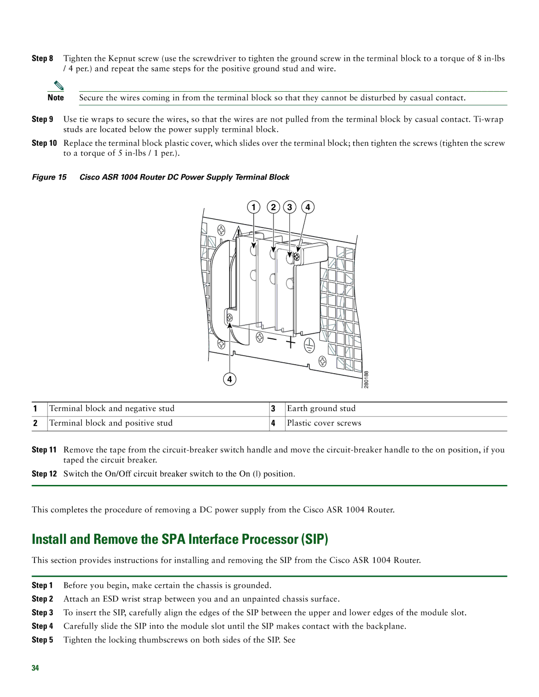
Figure 15 Cisco ASR 1004 Router DC Power Supply Terminal Block
1 2 3 4
4
280188
1 | Terminal block and negative stud | 3 | Earth ground stud |
|
|
|
|
2 | Terminal block and positive stud | 4 | Plastic cover screws |
|
|
|
|
Step 11 Remove the tape from the
Step 12 Switch the On/Off circuit breaker switch to the On () position.
This completes the procedure of removing a DC power supply from the Cisco ASR 1004 Router.
Install and Remove the SPA Interface Processor (SIP)
This section provides instructions for installing and removing the SIP from the Cisco ASR 1004 Router.
Step 1 Before you begin, make certain the chassis is grounded.
Step 2 Attach an ESD wrist strap between you and an unpainted chassis surface.
Step 3 To insert the SIP, carefully align the edges of the SIP between the upper and lower edges of the module slot. Step 4 Carefully slide the SIP into the module slot until the SIP makes contact with the backplane.
Step 5 Tighten the locking thumbscrews on both sides of the SIP. See
34