Step 2 After you establish normal router operation, you can disconnect the terminal.
Note For console and auxiliary port pinouts, see Appendix A in the Cisco ASR 1000 Series Aggregation Services Routers Hardware Installation and Initial Configuration Guide.
Management Ethernet Port Cable Connection
Before you can use the console interface on the router using a terminal or PC, you must perform the following steps:
Step 1 Configure your terminal emulation software with the following settings:
•9600 bits per second (bps)
•8 data bits
•No parity
•1 stop bit
•No flow control
Note For information about how to change the default settings to meet the requirements of your terminal or host, refer to the Cisco IOS Terminal Services Configuration Guide.
Step 2 Connect a terminal or PC to the console port using one of the following methods:
a.To connect to the console port using the cable and adapters provided in the accessory kit that shipped with your Cisco ASR 1000 Series Router:
–Place the console port mode switch in the in position (factory default).
–Connect to the port using the
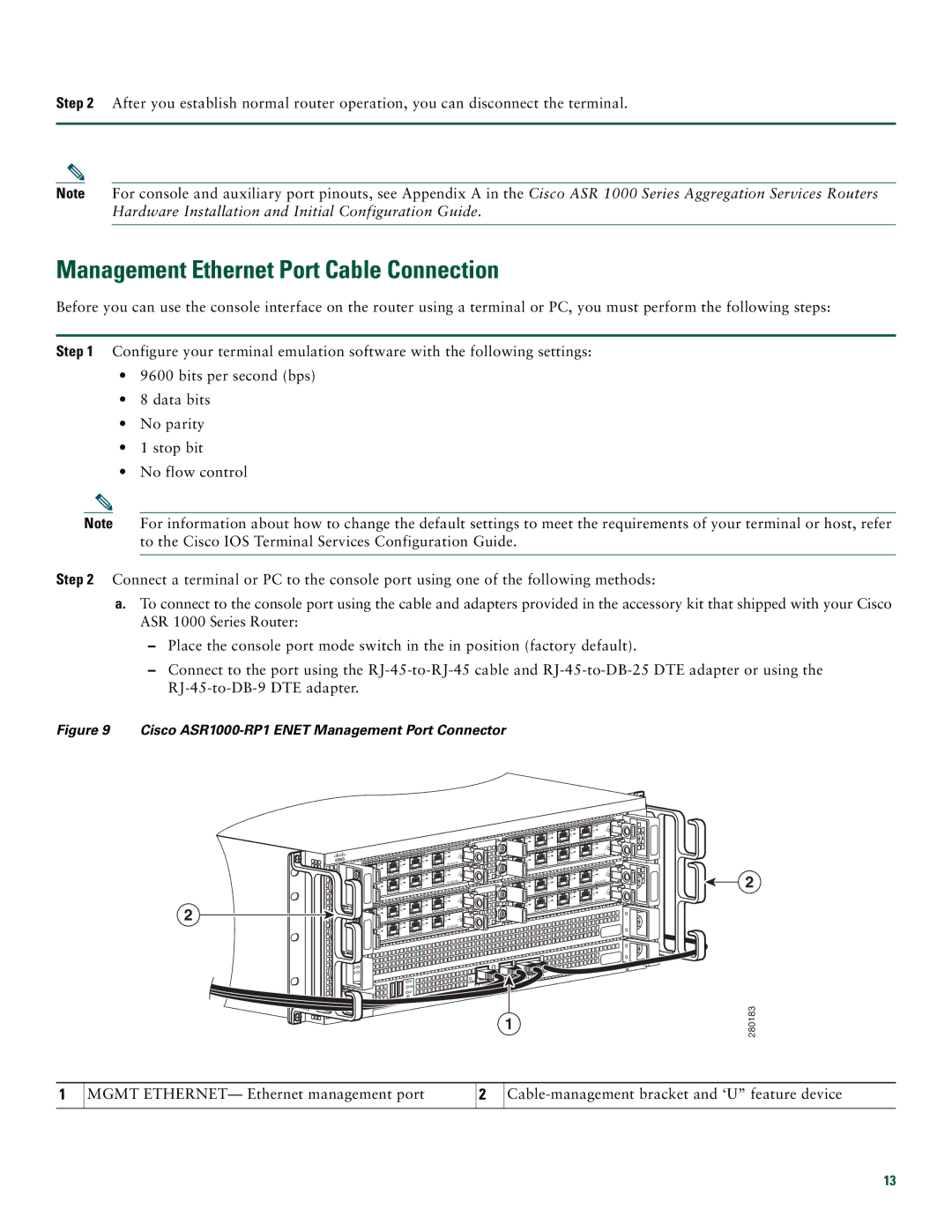
Figure 9 Cisco ASR1000-RP1 ENET Management Port Connector
2
| 2 |
| 1 |
| 0 |
2 | |
3 | 1 |
2 | 0 |
1 |
|
0 |
|
| |
3 |
|
2 | 2 |
1 | 1 |
0 | 0 |
2 | |
3 | 1 |
2 | 0 |
1 |
|
0 |
|
| |
3 |
|
2 |
|
1 |
|
0 |
|
|
|
|
|
|
|
|
|
| AUX |
|
|
|
|
|
| LINK |
|
| CON |
|
|
|
|
| HD | CARRIER | MGMT | E | E |
|
|
|
|
| USB | BITS |
|
|
|
|
| CRIT |
|
|
|
|
|
| |
|
|
|
|
|
|
|
|
| |
| ACTV | MAJ |
| O | DF |
|
|
|
|
PWR | AC | DISK |
|
|
|
| |||
STBY | MIN |
| 0 | 1 |
|
|
|
| |
STAT |
|
|
|
|
|
|
|
| |
ASR1000 |
|
|
|
|
|
|
|
|
1
![]() 3
3![]()
![]() 3
3
![]() 3
3
![]() 3
3
![]()
![]()
![]()
![]()
![]()
2
280183
1
MGMT ETHERNET— Ethernet management port
2
13