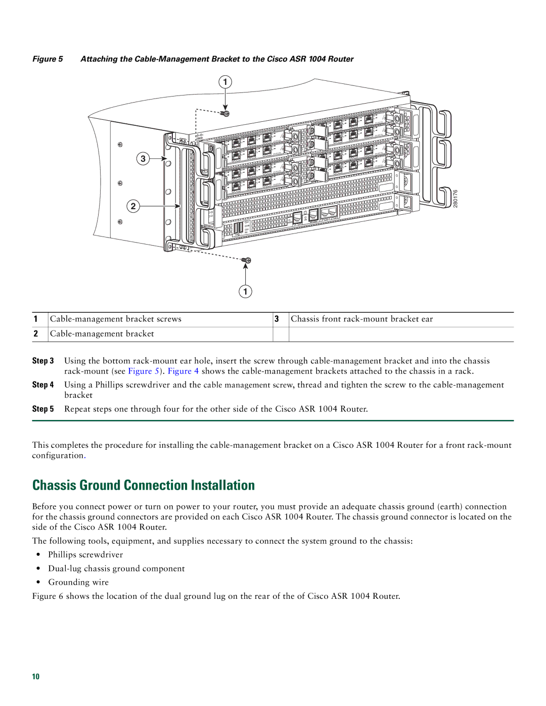
Figure 5 Attaching the Cable-Management Bracket to the Cisco ASR 1004 Router
1
3
|
|
|
| C/A |
C/A | C/A | A/L | ||
A | /L | 3 | ||
A/L |
|
| 2 | |
|
| 1 |
| C /A |
0 |
| C/A | A/L | |
|
| |||
C | /A | A | /L | 3 |
|
| |||
A | /L |
|
| 2 |
|
|
| ||
|
| 1 |
|
|
0 |
|
|
|
|
|
|
|
| C /A |
C/A | C/A | A/L | ||
A | /L | 3 | ||
A | /L |
|
| 2 |
|
| 1 |
| C/A |
|
|
|
| |
0 |
| C/A | A/L | |
|
| |||
C/ | A | A | /L | 3 |
|
| |||
A/L |
|
| 2 | |
|
| 1 |
|
|
0 |
|
|
|
|
C/ | A |
| TATUS | |
|
| |||
A | /L | S |
|
|
|
|
|
| |
C/A |
| T AT | US | |
A/L | S |
| ||
|
| |||
|
|
|
| |
C/ | A |
| TATUS | |
|
| |||
A | /L | S |
|
|
|
|
|
| |
C/ | A |
|
| US |
|
| T AT | ||
| /L | S |
| |
A |
|
| ||
|
|
|
| |
|
|
|
| C/A |
|
| C/ | A | A /L |
|
|
| ||
C/A | A | /L |
| |
A | /L |
|
| 2 |
|
|
| ||
|
| 1 |
| C/A |
0 |
| C/A | A /L | |
|
| |||
C | /A | A | /L |
|
|
| |||
A/L |
|
| 2 | |
|
| 1 |
|
|
0 |
|
|
|
|
|
|
|
| C/A |
|
| C/A | A/L | |
C/A | A/L |
| ||
A/L |
|
| 2 | |
|
| 1 |
| C/A |
0 |
| C/A | A/L | |
|
| |||
C/A | A | /L |
| |
A/L |
|
| 2 | |
|
| 1 |
|
|
0 |
|
|
|
|
C/ | A | TATUS |
A | /L | S |
|
|
|
| ||
3 |
|
|
|
|
|
C/A |
|
| T AT | US | |
| /L |
| S |
| |
A |
|
|
| ||
|
|
|
| ||
|
|
|
|
| |
3 |
|
|
|
|
|
C/ | A |
|
| TATUS | |
A | /L |
| S |
|
|
|
|
|
| ||
|
|
|
|
| |
3 |
|
|
|
|
|
C/ | A |
|
|
| US |
| /L |
| S | T AT |
|
A |
|
|
| ||
|
|
|
| ||
3 |
|
|
|
|
|
280176
2
|
|
|
|
|
|
| LINK |
| AUX |
|
|
|
|
|
|
|
| CON | |
|
|
|
|
|
| HD | CARRIER | MGMT | ETHERNET |
|
|
|
|
|
| USB | BITS |
|
|
|
| CRIT |
|
|
|
|
|
| |
|
|
|
|
|
|
|
|
| |
| ACTV | MAJ |
| O |
| DF |
|
|
|
PWR | AC |
| DISK |
|
|
| |||
|
|
|
|
|
| ||||
STBY | MIN |
|
| 0 | 1 |
|
|
| |
STAT |
|
|
|
|
|
| |||
|
|
|
|
|
|
|
| ||
ASR1000 |
|
|
|
|
|
|
|
| |
|
|
|
|
|
|
|
|
|
1
1
2
3 Chassis front |
Step 3 Using the bottom
Step 4 Using a Phillips screwdriver and the cable management screw, thread and tighten the screw to the
Step 5 Repeat steps one through four for the other side of the Cisco ASR 1004 Router.
This completes the procedure for installing the
Chassis Ground Connection Installation
Before you connect power or turn on power to your router, you must provide an adequate chassis ground (earth) connection for the chassis ground connectors are provided on each Cisco ASR 1004 Router. The chassis ground connector is located on the side of the Cisco ASR 1004 Router.
The following tools, equipment, and supplies necessary to connect the system ground to the chassis:
•Phillips screwdriver
•
•Grounding wire
Figure 6 shows the location of the dual ground lug on the rear of the of Cisco ASR 1004 Router.
10