Chapter 5 Troubleshooting
LED Summary
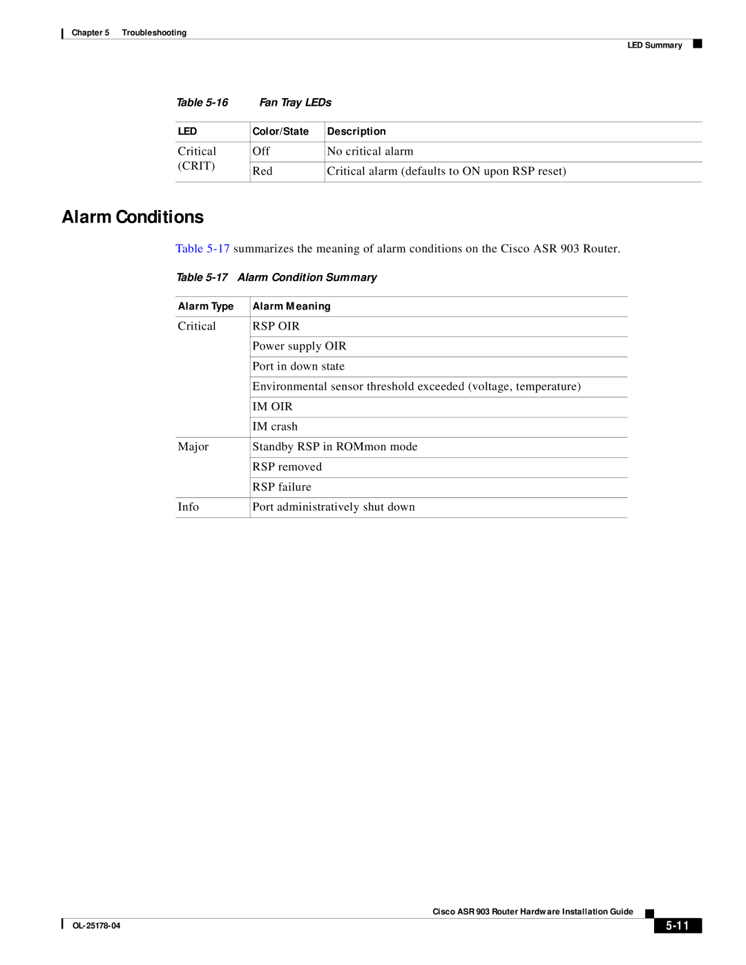
Table | Fan Tray LEDs | ||
|
|
| |
LED | Color/State | Description | |
|
|
| |
Critical | Off | No critical alarm | |
(CRIT) |
|
| |
Red | Critical alarm (defaults to ON upon RSP reset) | ||
| |||
|
|
| |
Alarm Conditions
Table
Table
Alarm Type | Alarm Meaning |
|
|
Critical | RSP OIR |
|
|
| Power supply OIR |
|
|
| Port in down state |
|
|
| Environmental sensor threshold exceeded (voltage, temperature) |
|
|
| IM OIR |
|
|
| IM crash |
|
|
Major | Standby RSP in ROMmon mode |
|
|
| RSP removed |
|
|
| RSP failure |
|
|
Info | Port administratively shut down |
|
|
|
| Cisco ASR 903 Router Hardware Installation Guide |
|
| |
|
|
| |||
|
|
|
|
| |
|
|
|
| ||