Chapter 3 Installing the Cisco ASR 903 Router
Installing the Chassis Ground Connection
Installing the Chassis Ground Connection
Before you connect the power or turn on the power to the Cisco ASR 903 Router, you must provide an adequate chassis ground (earth) connection to your router.
This section describes how to ground the Cisco ASR 903 Router chassis. The router provides two locations for attaching a
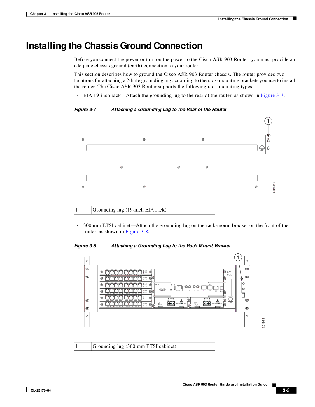
•EIA
Figure 3-7 Attaching a Grounding Lug to the Rear of the Router
1
281928
1
Grounding lug
•300 mm ETSI
Figure 3-8 Attaching a Grounding Lug to the Rack-Mount Bracket
1
|
|
|
|
|
|
|
|
|
| ||||||||
|
|
|
|
|
|
| PWR |
|
|
|
|
|
|
|
|
| FAN TEMP |
|
|
|
|
|
|
| STAT |
|
|
|
|
|
|
|
|
|
|
|
|
|
|
|
|
|
|
| CRIT MAJ MIN | ||||||||
|
|
|
|
|
|
| PWR |
|
|
|
|
|
|
|
|
|
|
|
|
|
|
|
|
| STAT |
|
|
|
|
|
|
|
|
|
|
|
|
|
|
|
|
|
|
|
| ||||||||
|
|
|
|
|
|
| PWR | RUDY RSP |
|
|
|
|
|
|
|
|
|
|
|
|
|
|
|
| STAT |
|
|
|
|
|
|
|
|
| SYNC |
|
|
|
|
|
|
|
|
|
|
|
|
|
|
|
|
| ACT |
|
|
|
|
|
|
| PWR |
|
| 1PPS | 1PPS | 1OMHZ | 1OMHZ |
|
|
| PWR |
|
|
|
|
|
|
| MEM | CONSOLE | IN | OUT | IN | OUT | TOD | BITS | MGMT | STAT | |
|
|
|
|
|
|
| STAT |
|
|
|
|
|
|
|
| ENET |
|
L 0 S | L 1 S | L 2 S | L 3 S | L 4 S | L 5 S | L 6 S | L 7 S |
|
|
|
|
|
|
|
|
|
|
|
|
|
|
|
|
| PWR |
|
|
|
|
|
|
|
|
|
|
|
|
|
|
|
|
| STAT |
|
|
|
|
|
|
|
|
|
|
L 0 S | L 1 S | L 2 S | L 3 S | L 4 S | L 5 S | L 6 S | L 7 S |
|
|
|
|
|
|
|
|
|
|
|
|
|
|
|
|
| PWR | INPUT |
|
|
|
| INPUT |
|
|
| ALARM |
|
|
|
|
|
|
| OK | 28A |
|
| OK |
|
| 28A | |||
|
|
|
|
|
|
|
| OUTPUT |
| OUTPUT |
|
| |||||
|
|
|
|
|
|
| STAT | FAIL |
|
|
| FAIL |
|
|
|
| |
L 0 S | L 1 S | L 2 S | L 3 S | L 4 S | L 5 S | L 6 S | L 7 S |
|
|
|
|
|
|
|
|
|
|
281929
1
Grounding lug (300 mm ETSI cabinet)
Cisco ASR 903 Router Hardware Installation Guide
|
| ||
|
|