Chapter 3 Installing the Cisco ASR 903 Router
Installing the Router in a Rack
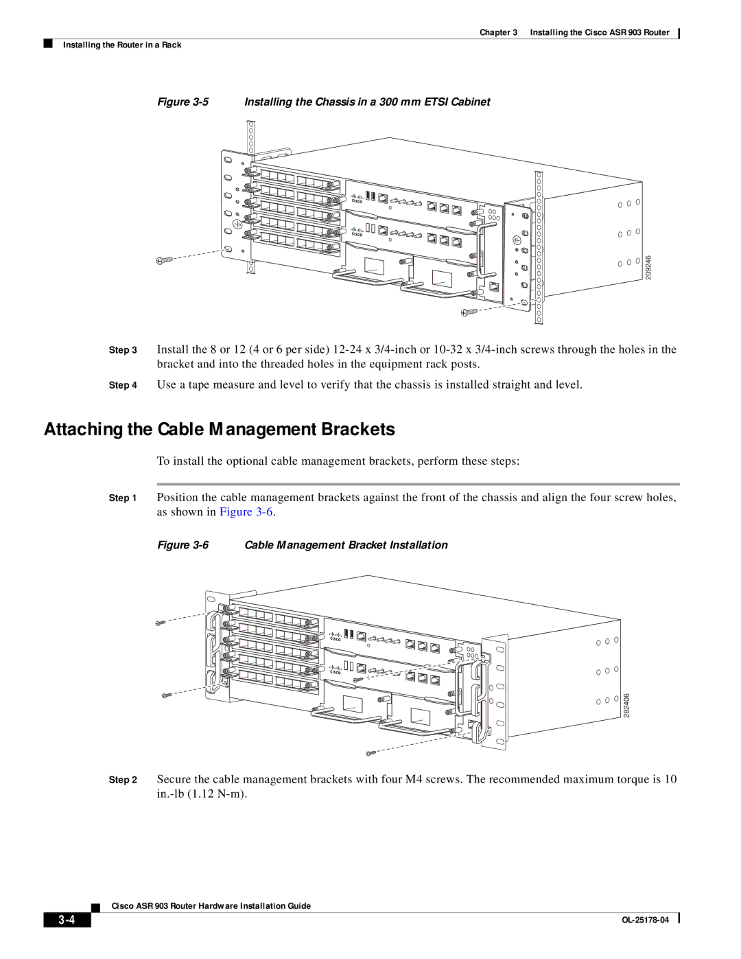
Figure 3-5 Installing the Chassis in a 300 mm ETSI Cabinet
209246
Step 3 Install the 8 or 12 (4 or 6 per side)
Step 4 Use a tape measure and level to verify that the chassis is installed straight and level.
Attaching the Cable Management Brackets
To install the optional cable management brackets, perform these steps:
Step 1 Position the cable management brackets against the front of the chassis and align the four screw holes, as shown in Figure
Figure 3-6 Cable Management Bracket Installation
282406
Step 2 Secure the cable management brackets with four M4 screws. The recommended maximum torque is 10
Cisco ASR 903 Router Hardware Installation Guide
|
| |
|
