Cisco Systems ASR 903 manual Connecting Cables to a GPS Interface, 3-38

Models: ASR 903

1 118
Download 118 pages 26.92 Kb
Page 88
Image 88
Connecting Cables to a GPS Interface

Chapter 3 Installing the Cisco ASR 903 Router

Connecting the Cisco ASR 903 Router to the Network

Connecting Cables to a GPS Interface

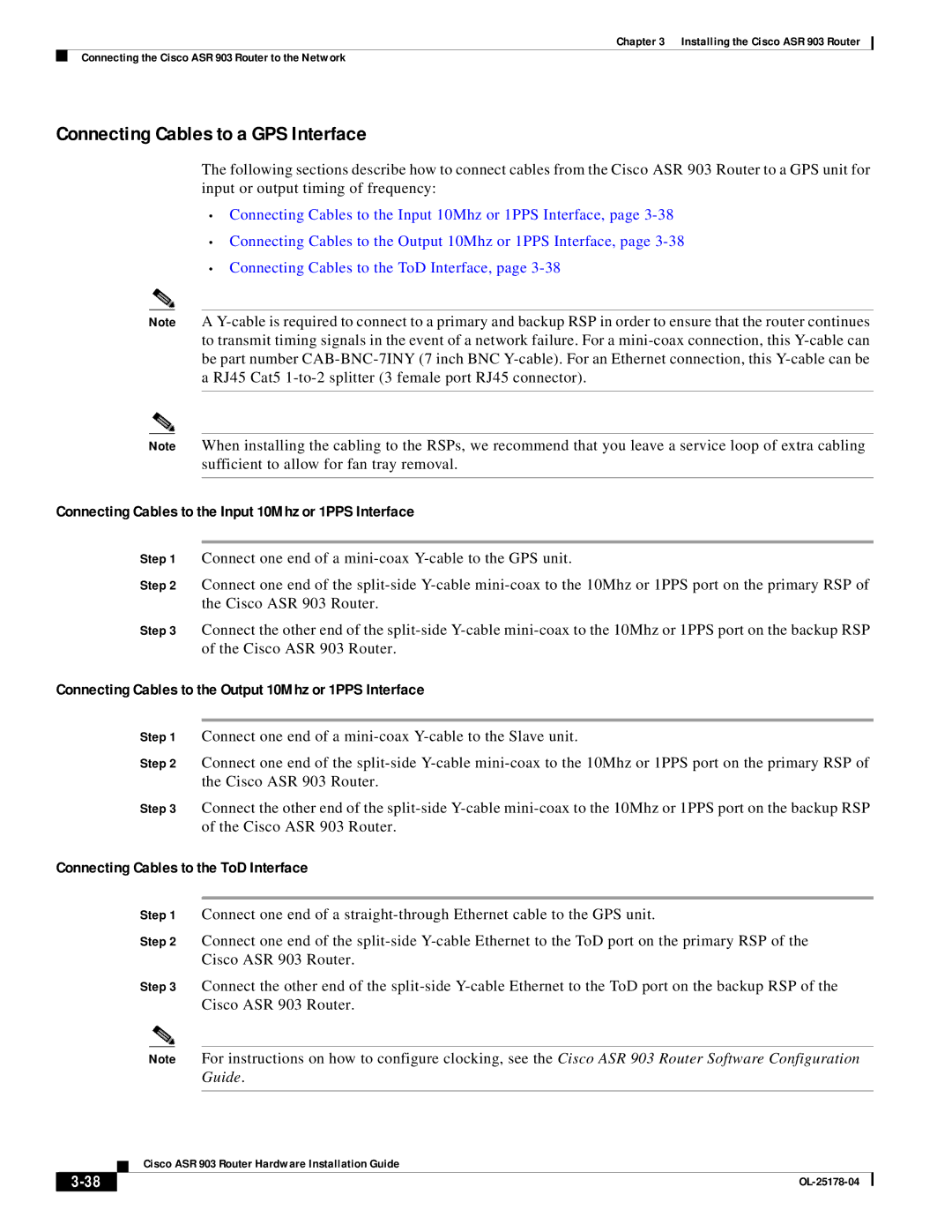
The following sections describe how to connect cables from the Cisco ASR 903 Router to a GPS unit for input or output timing of frequency:

Connecting Cables to the Input 10Mhz or 1PPS Interface, page 3-38

Connecting Cables to the Output 10Mhz or 1PPS Interface, page 3-38

Connecting Cables to the ToD Interface, page 3-38

Note A Y-cable is required to connect to a primary and backup RSP in order to ensure that the router continues to transmit timing signals in the event of a network failure. For a mini-coax connection, this Y-cable can be part number CAB-BNC-7INY (7 inch BNC Y-cable). For an Ethernet connection, this Y-cable can be a RJ45 Cat5 1-to-2 splitter (3 female port RJ45 connector).

Note When installing the cabling to the RSPs, we recommend that you leave a service loop of extra cabling sufficient to allow for fan tray removal.

Connecting Cables to the Input 10Mhz or 1PPS Interface

Step 1 Connect one end of a mini-coax Y-cable to the GPS unit.

Step 2 Connect one end of the split-side Y-cable mini-coax to the 10Mhz or 1PPS port on the primary RSP of the Cisco ASR 903 Router.

Step 3 Connect the other end of the split-side Y-cable mini-coax to the 10Mhz or 1PPS port on the backup RSP of the Cisco ASR 903 Router.

Connecting Cables to the Output 10Mhz or 1PPS Interface

Step 1 Connect one end of a mini-coax Y-cable to the Slave unit.

Step 2 Connect one end of the split-side Y-cable mini-coax to the 10Mhz or 1PPS port on the primary RSP of the Cisco ASR 903 Router.

Step 3 Connect the other end of the split-side Y-cable mini-coax to the 10Mhz or 1PPS port on the backup RSP of the Cisco ASR 903 Router.

Connecting Cables to the ToD Interface

Step 1 Connect one end of a straight-through Ethernet cable to the GPS unit.

Step 2 Connect one end of the split-side Y-cable Ethernet to the ToD port on the primary RSP of the Cisco ASR 903 Router.

Step 3 Connect the other end of the split-side Y-cable Ethernet to the ToD port on the backup RSP of the Cisco ASR 903 Router.

Note For instructions on how to configure clocking, see the Cisco ASR 903 Router Software Configuration Guide.


Cisco ASR 903 Router Hardware Installation Guide

3-38

OL-25178-04

Page 88
Image 88
Cisco Systems ASR 903 Connecting Cables to a GPS Interface, Connecting Cables to the Input 10Mhz or 1PPS Interface, 3-38