Cisco Systems, Inc
Page
Review Draft Cisco Confidential
Memory
Installing the 3G Adapter for Extended Cable/Antenna
Cable Specifications A-11
Audience
Objective
Conventions
Organization
Chapter Name Description
Warnung Wichtige Sicherheitshinweise
Bewaar Deze Instructies
Aviso Instruções Importantes DE Segurança
Avvertenza Importanti Istruzioni Sulla Sicurezza
OL-16215-11
GEM Disse Anvisninger
Vii
Viii
Related Documentation
Searching Cisco Documents
Obtaining Documentation and Submitting a Service Request
Product Overview
Cisco 860 Series ISRs
General Description
LEDs
Model Interfaces
FE 1 switch ports GE 2 switch port GE WAN port
Cisco 860VAE Series ISRs
Interfaces
VDSL/ADSL over Pots port VDSL/ADSL over Isdn port
IOS Images
Model IOS Image
4shows the back panel details of the Cisco 866VAE ISR
C866VAE-W-E C867VAE-W-A C867VAE-W-E
Model-Specific Features
Common Features
Feature
Port
Interface Connector
Port Label
GE LAN
Port LED Color Description
FE LAN
Green Off-No link Faster flashing indicates heavier traffic
LED indicators
LED Indicators on Front Panel
LED Color LED Activity Description
Cisco 880 Series Data Routers
Cisco 880 Series ISRs
Isdn
9shows the back panel details of the Cisco 886VA data router
10 Back Panel of the Cisco 887VA and 887VA-M Router
Primary WAN port-VDSL/ADSL over Reset button
Cisco 881 Srst and Cisco 888 Srst
Cisco 880 Series Voice and Data Routers
LEDs USB port
13 Back Panel of the Cisco C881SRST-W Voice Router
14 Back Panel of the Cisco C888SRST-W Voice Router
C881-V C887VA-V C887VA-V-W
Flexible Complexity Medium Complexity High Complexity
LEDs USB port
17shows the back panel for the Cisco 881-V router
PoE power connector optional
Cisco 887VA-WD
Cisco 880 Series with Embedded Wlan Antennas
C881WD
Cisco 891, Cisco 892, and Cisco 892F
Cisco 890 Series ISRs
LEDs USB ports
22 Front Panel of the Cisco 890 Series Wireless ISR
23 Back Panel of the Cisco 892-W Router
SFP port SFP LEDs
Cisco 892FSP, Cisco 896VA, Cisco 897VA, and Cisco 898EA
25shows the back panel of the Cisco 892FSP router
27shows the back panel of the Cisco 896VA router
29shows the back panel of the Cisco 897VA router
31shows the front panel of the Cisco 897VAM router
34shows the back panel of the Cisco 897VAMW router
35shows the back panel of the Cisco 898EA router
Reset Button
Hardware Features
Kensington Lock
Product Overview Hardware Features
Product Overview Hardware Features
Color Description Series
LEDs
PPP3
Wlan Link
VPN
Green On-VPN is connected All models
Srst
3G8 WWAN9
3G RSSI10
3G CDMA12
SFP S
SFP14 EN
Activity Description
XDSL Link
GE Mode
Activity
Color Activity Description
Flash Memory
Memory
Models Flash Memory Storage
Expandability
USB Port
Main Memory
Models
Power over Ethernet Module
Power Supply
Fan
3G Cellular Data WAN Connectivity
Throughput1 Mode Antenna
Wireless LAN Connectivity
Maximum Data Radio Module Platform
AIR-ANTM4050V-R
Small Form-Factor Pluggable Port
Cisco Part Number Antenna Type Maximum Gain Description
AIR-ANTM2050D-R
Feature Description Series
Feature Summary
RTC
FXS19/DID20
SRST17
Product Overview Hardware Features
Indoors. Statement
No user-serviceable parts inside. Do not open. Statement
Statement
Cisco 860VAE Series Routers
Equipment, Tools, and Connections
Items Shipped with your Router
Additional Items
Connections
Installing the Router
Ethernet Devices
Installing Antennas
Attaching Antennas to the Router
Antennas Oriented Vertically Up
Antennas Oriented Vertically Down
Installing on a Table
Mounting on a Wall
Wall-mount Holes on the Underside of the Router
Router Mounted on the Wall
Installing in a Rack
Installing the Router
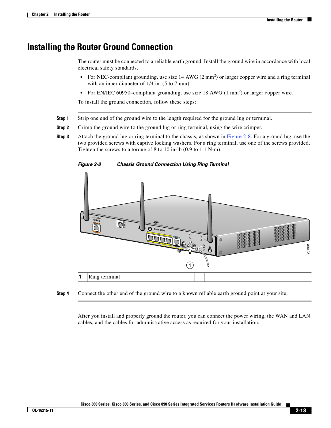
Chassis Ground Connection Using Ring Terminal
Installing the Router Ground Connection
Installing the Fips Cover
Install the left-side Fips cover, as shown in detail a
Secure the Fips cover with two mounting screws
284925
Installing the Router
Connecting the Router
Safety Warnings
Connecting the Router Safety Warnings
Preventing Damage to the Router
Preparing to Connect the Router
Connecting a Server, PC, or Workstation
Connecting a PC, Server, or Workstation
Connecting a Phone
Connecting a Phone
Connecting to an Ethernet Switch
Connecting an External Ethernet Switch
Connecting to Your Service Provider Through the V.92 port
Connecting the V.92 modem Port
Connecting a Terminal or PC to the Console Port
Connecting a Terminal or PC to the Console Port
Terminal Emulator Settings
Connecting a Modem to the Auxiliary Port
Connecting the 3G Card
Inserting the 3G Card
Pins on the locking bracket for alignment
3G card Notch on the 3G card Locking bracket
Installing the Locking Bracket
10 Closing the Locking Bracket
Close the locking bracket, as shown in Figure
12 Antenna connected to the 3G Card with Ssmb connector
Description SKUs Supported
14 Locating the Phillips Screw
Installing the 3G Adapter for Extended Cable/Antenna
Hooks aligned and inserted into the router
Locate the hooks on the adapter as shown in Figure
17 Attaching the Adapter
18 Adapter Connected to 3G Card and Router Chassis
Inches 62 dB 2100
Connecting a Data BRI Port
Inches 66 dB 2100
3G-ACC-TS9-TNC
19 Connecting the Data BRI Port to the Isdn Line
20 Connecting the FE WAN Port
Connecting an FE Line to an FE WAN Port
21 Connecting the GE WAN Port
Connecting a GE Line to an GE WAN Port
Connecting an xDSL Line
22 Primary Protection Device Location
Connecting Power over Ethernet
120 VAC, 20 a U.S VAC, 16 to 20 a international. Statement
Connecting the AC Adapter
25 Connecting the AC Adapter
VDC plug Power adapter-12 VDC Power cord AC plug
NC1
VDC plug Power adapter-12 VDC Power Adapter Cord AC Plug
Pin
Ground
28 Securing the Power Cord
Power lock clip Power adapter Power cord AC plug
Connecting an FXS Line
30 Connecting an FXS Line
31 Connecting an FXO Line
Connecting an FXO Line
Connecting a Voice Isdn BRI Line
32shows a voice BRI line connection
Safety Warnings
Connecting a Small Form-Factor Pluggable Module
Laser Safety Warnings
Removing an SFP Module
Installing an SFP Module
Connect the network cable to the SFP module
Online Insertion and Removal
34 -42 Disconnecting SFP Latch Mechanisms
LEDs to Check Normal Patterns
Verifying Connections
LAN
Faster blinking when there is heavier traffic
On when DSL WAN mode is selected and DSL training
On when the DSL interface is up
Blinking when there is DSL WAN activity traffic in either
Cisco IOS CLI
Cisco Configuration Professional Express
IOS CLI
Press Return. The following message is displayed
Following message is displayed
Setup Command Facility
Enter interface name used to connect to
Enter a hostname for the router this example uses Router
Configuration is displayed
Verifying the Initial Configuration
Initial Configuration of the Wireless Access Point
Technical Specifications
All Models Except Cisco 860VAE Series
Router Specifications
AC Adapter
Cisco 860VAE Series
PWR-30W-AC
Sound Pressure Convection cooled, no fan
Description Specification
Description Cisco 860VAE series
Enclosure X 9 x 1.75 in. W x D x H
Description Design Specification
Power Supply
Wireless Access Point
Power Supply Unit Volt
Pin LAN and WAN
GE Signal
FE and GE Port Pinouts
Pin Function
FXS and FXO Port Connector Pinouts
Console and Auxiliary Port Connector Pinouts
VDSL2 Port Connector Pinouts
RJ-11 Pin
ADSL2+ Port Connector Pinouts
Port Connector Pinouts
Shdsl Port Connector Pinouts
TXN
Data BRI Port Connector Pinouts
TXP
RXP
Voice Isdn BRI Interface Pin Numbers and Functions
SFP Port Connector Pinouts
Isdn BRI NT/TE Card NT Interface TE Interface
Type Category
Cable Specifications
Ethernet Cable Specifications
Maximum Cable Length
OL-16215-11