Chapter 1 Product Overview
Front Panel
Table | System LED (continued) | |
|
|
|
Color |
| System Status |
|
|
|
Green |
| System is operating normally. |
|
|
|
Amber |
| System is receiving power but is not functioning properly. |
|
|
|
1. POST =
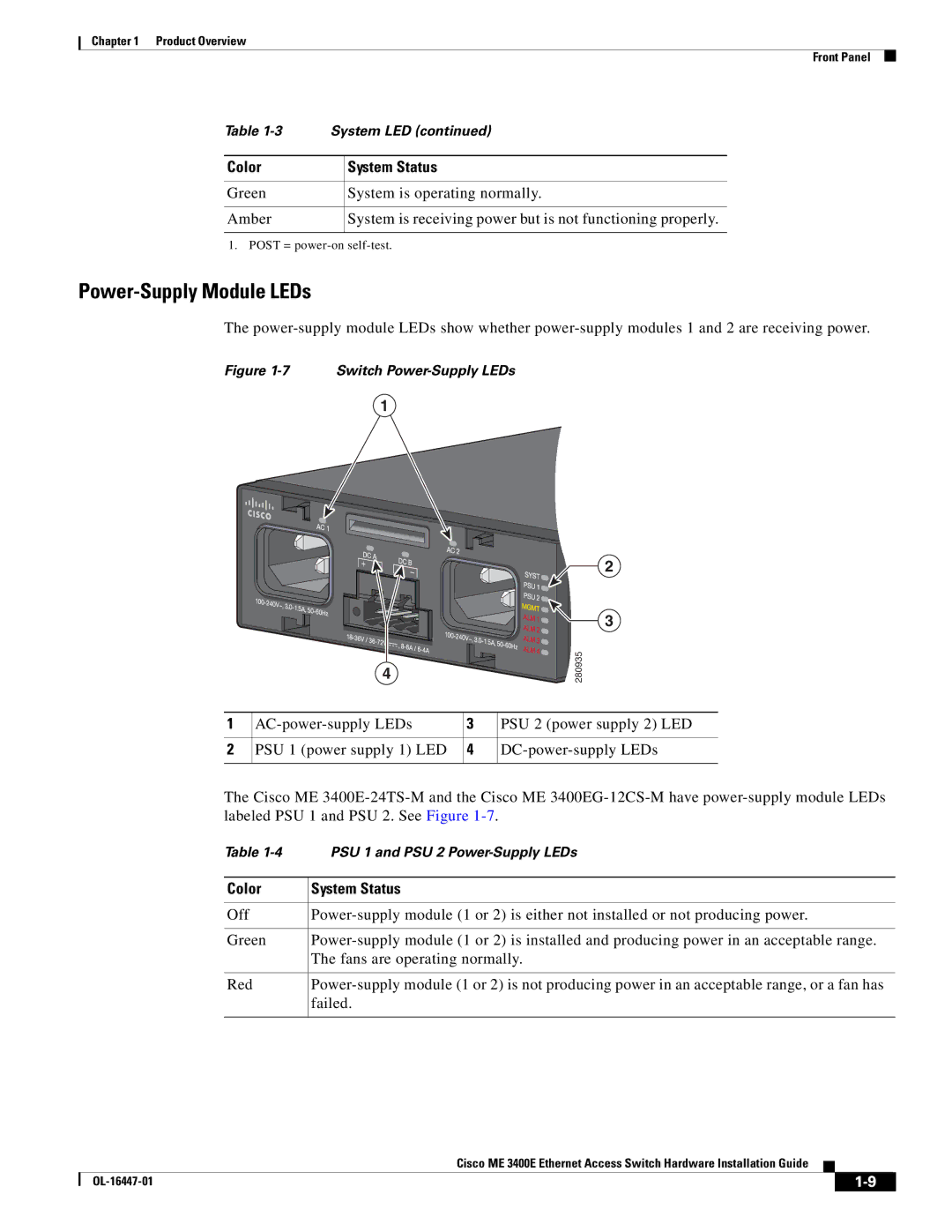
Power-Supply Module LEDs
The
Figure 1-7 Switch Power-Supply LEDs
1
4
![]() 2
2
![]()
![]()
![]()
![]()
![]()
![]() 3
3
280935
1 | 3 | PSU 2 (power supply 2) LED | |
|
|
|
|
2 | PSU 1 (power supply 1) LED | 4 | |
|
|
|
|
The Cisco ME
Table | PSU 1 and PSU 2 |
|
|
Color | System Status |
|
|
Off | |
|
|
Green | |
| The fans are operating normally. |
|
|
Red | |
| failed. |
|
|
Cisco ME 3400E Ethernet Access Switch Hardware Installation Guide
|
| ||
|
|