Chapter 3 Installing and Removing AC- and
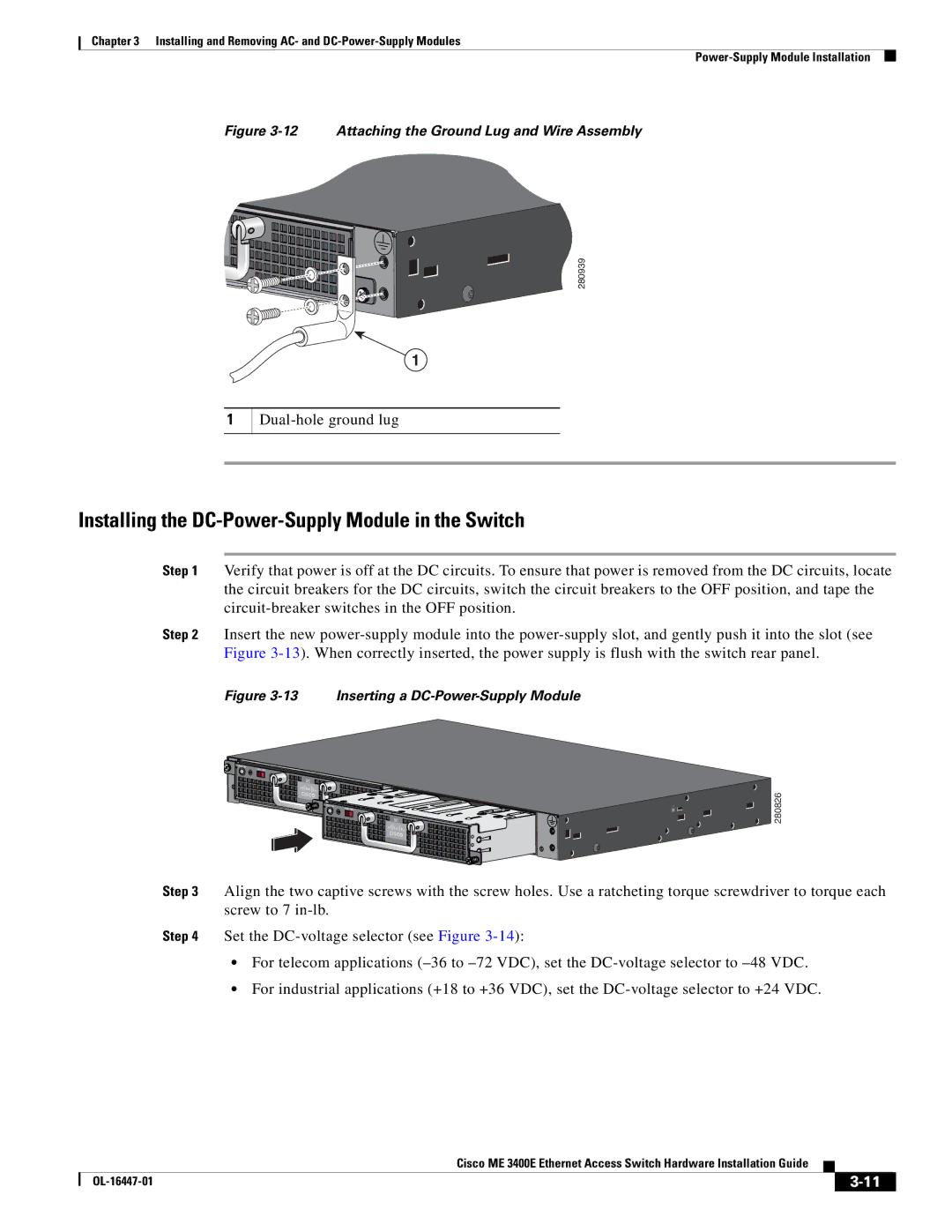
Figure 3-12 Attaching the Ground Lug and Wire Assembly
280939
1
1
Installing the DC-Power-Supply Module in the Switch
Step 1 Verify that power is off at the DC circuits. To ensure that power is removed from the DC circuits, locate the circuit breakers for the DC circuits, switch the circuit breakers to the OFF position, and tape the
Step 2 Insert the new
Figure 3-13 Inserting a DC-Power-Supply Module
PSU OK | +24V |
|
DC |
|
PSU OK | +24V |
|
DC
280826
Step 3 Align the two captive screws with the screw holes. Use a ratcheting torque screwdriver to torque each screw to 7
Step 4 Set the
•For telecom applications
•For industrial applications (+18 to +36 VDC), set the
|
| Cisco ME 3400E Ethernet Access Switch Hardware Installation Guide |
|
| |
|
|
| |||
|
|
|
| ||
|
|
|
| ||