Chapter 2 Switch Installation
Installing the Switch
After the switch is mounted in the rack, you need to do these tasks to complete the installation:
•Power on the switch. See the “Verifying Switch Operation” section on page
•Connect to the
•Connect to the
•We recommend attaching the cable guide to prevent the cables from obscuring the front panel of the switch and the other devices installed in the rack. Use the supplied black screw shown in Figure
For configuration instructions about using the CLI setup program, go to Appendix C, “Configuring the Switch with the
Wall-Mounting
•Attaching Brackets for
•Mounting the Switch on a Wall, page
Note
Attaching Brackets for Wall-Mounting
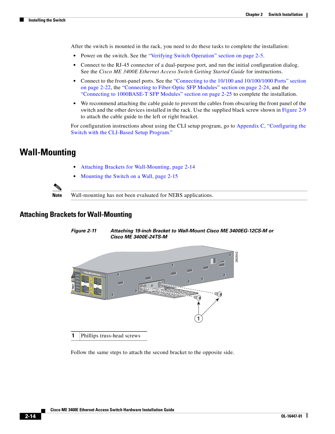
Figure 2-11 Attaching 19-inch Bracket to Wall-Mount Cisco ME 3400EG-12CS-M or
Cisco ME 3400E-24TS-M
280842
1
1
Phillips
Follow the same steps to attach the second bracket to the opposite side.
| Cisco ME 3400E Ethernet Access Switch Hardware Installation Guide |