Chapter 2 Switch Installation
Connecting to the 10/100 and 10/100/1000 Ports
Follow these steps to connect to
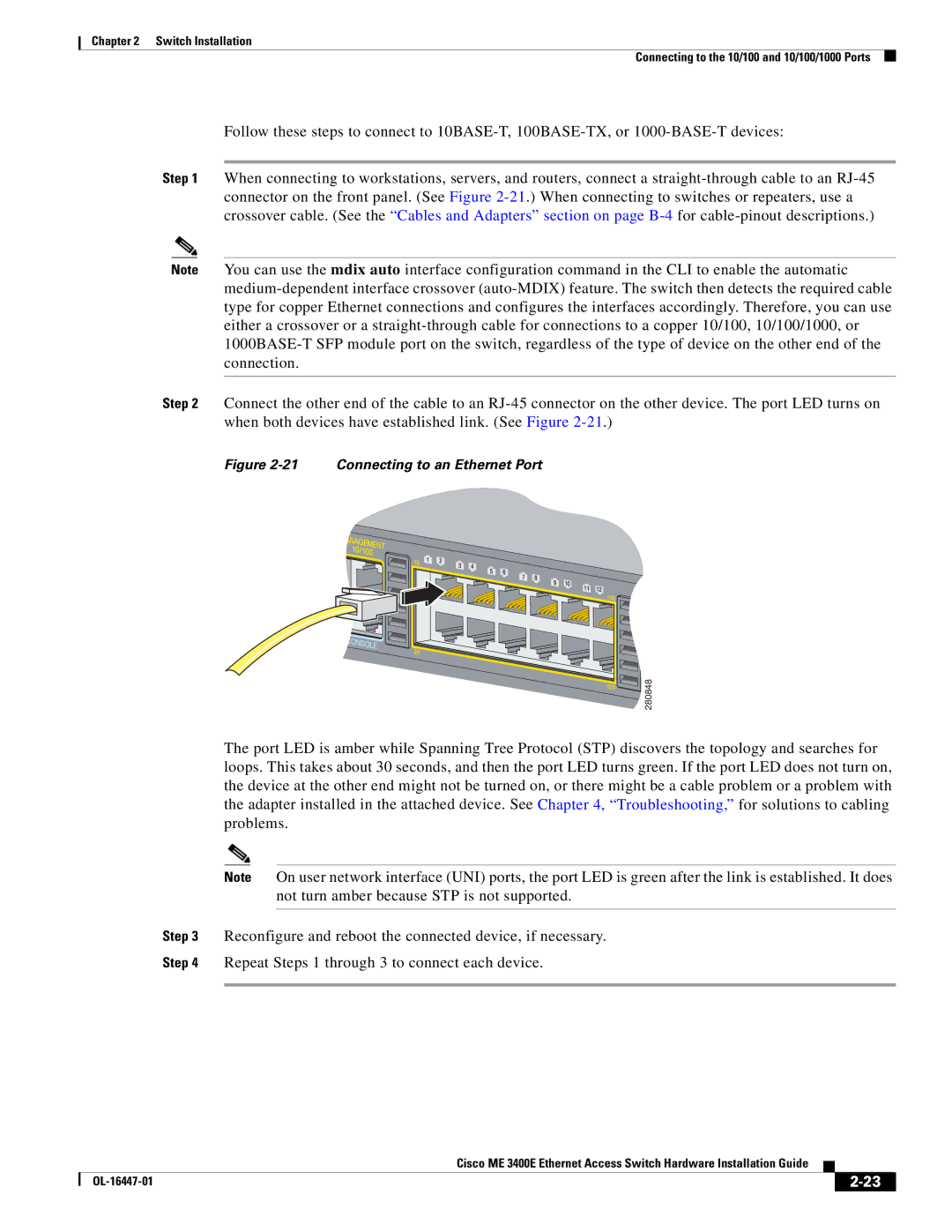
Step 1 When connecting to workstations, servers, and routers, connect a
Note You can use the mdix auto interface configuration command in the CLI to enable the automatic
Step 2 Connect the other end of the cable to an
Figure 2-21 Connecting to an Ethernet Port
280848
The port LED is amber while Spanning Tree Protocol (STP) discovers the topology and searches for loops. This takes about 30 seconds, and then the port LED turns green. If the port LED does not turn on, the device at the other end might not be turned on, or there might be a cable problem or a problem with the adapter installed in the attached device. See Chapter 4, “Troubleshooting,” for solutions to cabling problems.
Note On user network interface (UNI) ports, the port LED is green after the link is established. It does not turn amber because STP is not supported.
Step 3 Reconfigure and reboot the connected device, if necessary.
Step 4 Repeat Steps 1 through 3 to connect each device.
|
| Cisco ME 3400E Ethernet Access Switch Hardware Installation Guide |
|
| |
|
|
| |||
|
|
|
| ||
|
|
|
| ||