Chapter 3 Installing and Removing AC- and
Figure 3-5 Blank Cover Installed on the Power-Supply Slot
PSU OK | +24V |
|
DC
![]()
 280948
Installing an AC-Power-Supply Module
This procedure is for installing an
Note If you operate the switch with two power supplies, enter the
Each
Figure 3-6 AC-Power-Supply Diagram
AC-1 
PSU-1
AC-2 
PSU-2
2 098 73
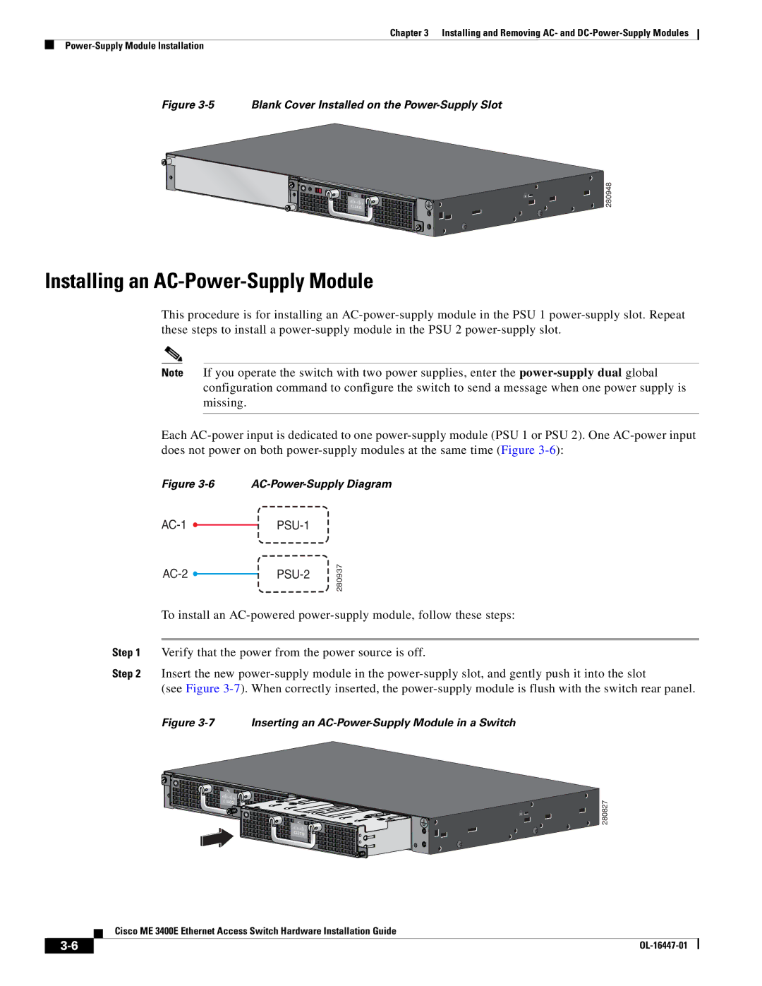
To install an
Step 1 Verify that the power from the power source is off.
Step 2 Insert the new
(see Figure
Figure 3-7 Inserting an AC-Power-Supply Module in a Switch
PSU OK![]()
AC
![]()
![]() PSU OK
PSU OK![]()
![]()
![]()
![]()
![]()
![]()
AC
 280827
Cisco ME 3400E Ethernet Access Switch Hardware Installation Guide
|
| |
|