Chapter 3 Installing and Removing AC- and
Table | PSU OK LED Descriptions | |
| ||
| ||
|
|
|
LED |
| Description |
|
|
|
Off |
| No input power. |
|
|
|
Green |
| Operating normally. Input, |
|
|
|
Red |
| Fault detected: |
|
| |
| ||
|
|
|
LED |
| Description |
|
|
|
Off |
| No input power. |
|
|
|
Green |
| Operating normally. Input, |
|
|
|
Red |
| Fault detected: |
|
|
|
Connector-Side Description
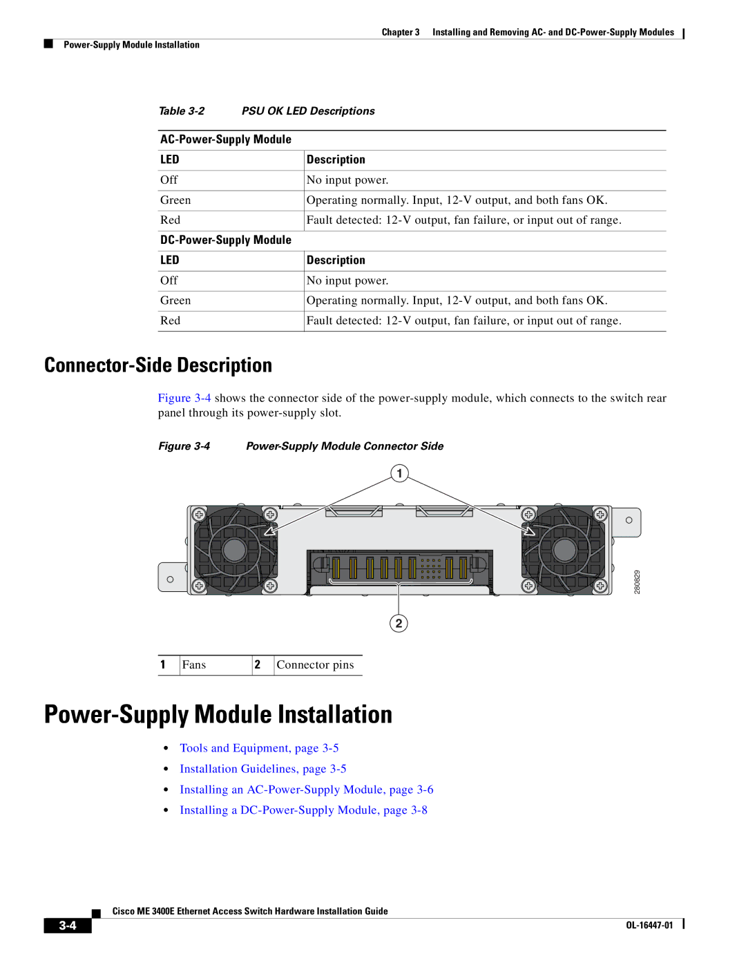
Figure 3-4 shows the connector side of the power-supply module, which connects to the switch rear panel through its power-supply slot.
Figure 3-4 Power-Supply Module Connector Side
1
280829
2
1
Fans
2
Connector pins
Power-Supply Module Installation
•Tools and Equipment, page
•Installation Guidelines, page
•Installing an
•Installing a
Cisco ME 3400E Ethernet Access Switch Hardware Installation Guide
|
| |
|