1-12
Cisco ME 3400E Ethernet Access Switch Hardware Installation Guide
OL-16447-01
Chapter 1 Product Overview
Rear Panel
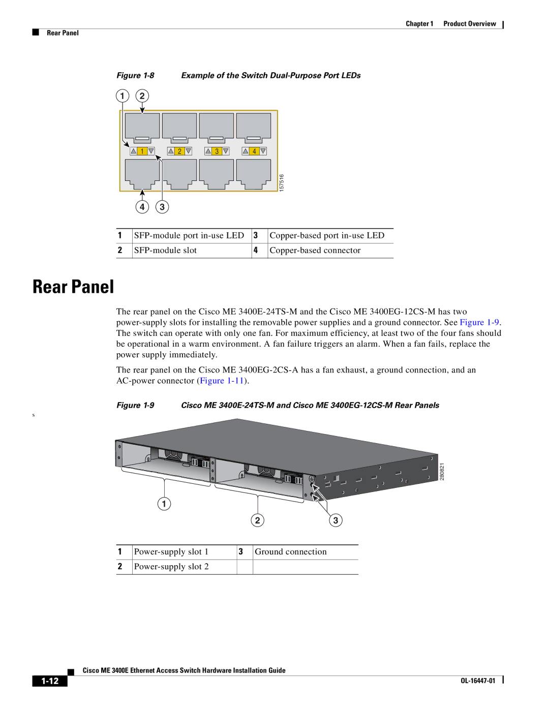
Figure 1-8 Example of the Switch Dual-Purpose Port LEDs
Rear Panel
The rear panel on the Cisco ME 3400E-24TS-M and the Cisco ME 3400EG-12CS-M has two
power-supply slots for installing the removable power supplies and a ground connector. See Figure 1-9.
The switch can operate with only one fan. For maximum efficiency, at least two of the four fans should
be operational in a warm environment. A fan failure triggers an alarm. When a fan fails, replace the
power supply immediately.
The rear panel on the Cisco ME 3400EG-2CS-A has a fan exhaust, a ground connection, and an
AC-power connector (Figure 1-11).
Figure 1-9 Cisco ME 3400E-24TS-M and Cisco ME 3400EG-12CS-M Rear Panels
s
1SFP-module port in-use LED 3Copper-based port in-use LED
2SFP-module slot 4Copper-based connector
1234
4
2
157516
3
1
1Power-supply slot 1 3Ground connection
2Power-supply slot 2
1
2
280821
3