This Document
Important Safety Instructions
Important Safety Instructions
Aviso a los instaladores de sistemas Catv
Mitteilung für CATV-Techniker
Power Source Warning
Ground the Product Protect the Product from Lightning
Verify the Power Source from the On/Off Power Light
Protect from Exposure to Moisture and Foreign Objects
Protect the Product When Moving It
Service Warnings Check Product Safety
United States FCC Compliance
FCC Compliance
Declaration of Conformity
Canada EMI Regulation
Canada
Radiation Exposure Statements
Australia
Introduction
Benefits and Features
Introduction
Allows automatic software upgrades by your service provider
Whats In the Carton?
Front Panel Description
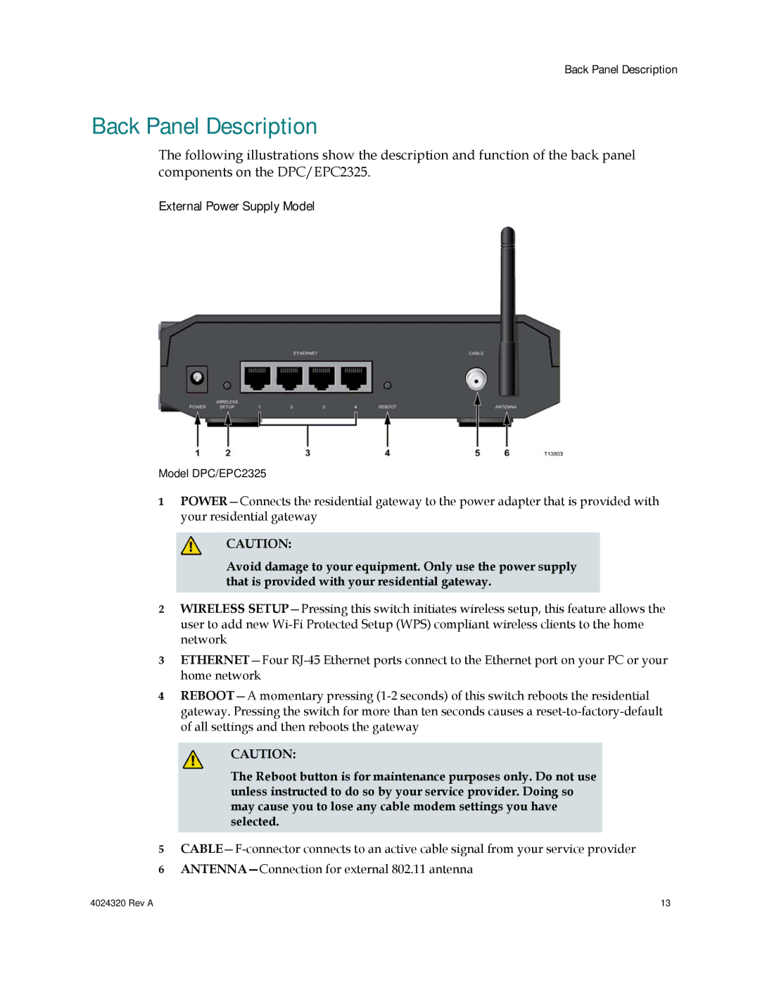
Back Panel Description
External Power Supply Model
Rev a
Before You Begin
How Do I Mount the Modem on a Wall? Optional
How Do I Mount the Modem on a Wall? Optional
Mounting the Residential Gateway on a Wall
Location and Dimensions of the Wall-Mounting Slots
Minimum System Requirements for a PC
What Are the System Requirements for Internet Service?
Minimum System Requirements for Macintosh
System Requirements for an Ethernet Connection
Do Not Have a High-Speed Internet Access Account
How Do I Subscribe to High-Speed Internet Service?
Already Have an Existing High-Speed Internet Access Account
How Do I Connect My Devices to Use the Internet?
Connecting and Installing Internet Devices
To connect devices
Connecting the Modem for High-Speed Data Service
About Your Modem Page Example
How Do I Configure My Docsis Residential Gateway?
About Your Modem Page Description
Accessing the Residential Gateway
Software File Name and Revisions Section
First Time Users
Setting Configuration Options
Setup Page Section Headings
Setup
Advanced Settings
Basic Settings
Firewall
Parental Control
Wireless
Setup Basic Settings Password Settings
Configuring Your Password Settings
To set up your password
How Do I Configure My Docsis Residential Gateway?
Configuring Network Time Synchronization
Key Description
Function Keys
How Do I Configure My Docsis Residential Gateway?
Setup Basic Settings Network Configuration
Configuring the Network Settings
Setup Basic Settings Network Configuration Page Description
MAC
DNS
Setup Basic Settings IP Management Page Example
Configuring and Managing IP Addresses
Setup Basic Settings IP Management Page Description
Function Keys
Reserving IP Addresses
Setup Basic Settings Fixed CPE IP Assignment
Field Name Description
Restarting the Gateway Modem
Setup Basic Settings Restart Cable Modem
Setup Basic Settings Save RG Configuration to Local PC
Saving Your Configuration
Setup Advanced Settings Options
Enabling and Disabling Advanced Features
Setup Advanced Settings Options Page Description
Field Name Description
Setup Advanced Settings IP Filtering
Configuring IP Address Filters
Setup Advanced Settings IP Filtering Page Description
Setup Advanced Settings MAC Filtering
Configuring MAC Address Filters
Setup Advanced Settings MAC Filtering Page Description
Setting Up MAC Address Filters
Setup Advanced Settings Port Filtering
Configuring and Enabling TCP and UDP Port Filters
Setup Advanced Settings Port Filtering Page Description
Setup Advanced Settings Port Forwarding
Configuring Port Forwarding for Local IP Addresses
Setup Advanced Settings Port Forwarding Page Description
How Do I Configure My Docsis Residential Gateway?
Setup Advanced Settings Port Triggers
Configuring TCP/UDP Port Triggers
Setup Advanced Settings Port Triggers Page Description
Setup Advanced Settings DMZ Host
Configuring the DMZ Host
Setup Advanced Settings DMZ Host Page Description
Configuring VPN Termination
New Tunnel, the VPN Setup page opens
Setup Advanced Settings VPN Termination Status
Creating and Configuring IPsec VPN Tunnels
Tunnel Section
Setup Advanced Settings VPN Setup Page Description
Local Endpoint Settings
Remote Endpoint Settings
Fqdn
IPsec Settings
Field
MD5 SHA
Setup Firewall Options
Configuring Firewall Protection
Setup Firewall Options Page Description
Field Name Description
Setup Firewall Event Logging
Configuring Firewall Event Logging and E-mail Alerts
Setup Firewall Event Logging Page Description
Key
Setup Parental Control User Setup
Configuring Parental Control
Setup Parental Control User Setup Page Description
How Do I Configure My Docsis Residential Gateway?
Function Keys
Setup Parental Control Basic Setup
Configuring Parental Control Basic Rules
Setup Parental Control Basic Setup Page Description
ORG, or .GOV extension
To use Keyword and Domain Blocking
Setup Parental Control Time of Day Access Filter
Configuring Parental Control Time of Day Access Filters
Function Keys
Setup Parental Control Event Log
Configure Parental Control Event Reporting
Setup Parental Control Event Log Page Description
Setup Wireless Basic
Configuring Your Wireless Access Point Parameters
Setup Wireless Basic Page Description
Field Name Description
Using Wi-Fi Protected Setup WPS
Setup Wireless Security Page Description
Setup Wireless Security
TKIP-AES
Subscribe to High-Speed Internet Service? on page 19 for
Field Name Description
Field Name Description
WPS Setup AP Section
Wi-Fi Protected Setup WPS Section
Keys Description
WPS Add Client Section
Setup Wireless Advanced Page Example
Configuring Wireless Data Rates and Wi-Fi Thresholds
Setup Wireless Advanced Page Description
How Do I Configure My Docsis Residential Gateway?
Field Name Description
Setup Wireless Access Control
Configuring Wireless Access Point Access Control
Setup Wireless Access Control Page Description
Function Keys
Setup Wireless Access Control Page Example
Configuring Remote Bridges
Setup Wireless Bridging Page Description
Cannot connect to the Internet
How Do I Troubleshoot My Internet Service Installation?
My residential gateway does not recognize the cable network
How many Ethernet network devices can I connect?
Frequently Asked Questions
What are the requirements for wireless networking?
Renewing the IP Address on Windows NT, 2000, or XP Systems
How do I renew the IP address on my PC?
Configuring TCP/IP on Windows 2000 Systems
Configuring TCP/IP on Windows XP Systems
Configuring TCP/IP on Macintosh Systems
Configuring TCP/IP on Windows 95, 98, 98SE, or ME Systems
What if I dont subscribe to cable TV?
Can I watch TV and surf the Internet at the same time?
Having Difficulty?
Common Troubleshooting Issues
Check and Correct
Tips for Improved Performance
High Speed Data Registration
Front Panel LED Status Indicator Functions
Front Panel LED Status Indicators During Normal Conditions
Normal Operations AC Power applied
Special Conditions
Front Panel LED Status Indicators During Special Conditions
If You Have Questions
For Information
Disclaimer
Trademarks
Documentation Copyright Notice
Software and Firmware Use
Win32 Ipsec Layer from SSH
Broadcom
OpenSSL
SSLeay License
OpenSSL License
Rev a 113
ECos
Mini-HTTPD
GNU General Public License Version 2, June
116 Rev a
Rev a 117
118 Rev a
Kerberos
Part 1 CMU/UCD Copyright Notice BSD like
NetSNMP
Rev a 121
Part 4 Sun Microsystems, Inc. Copyright Notice BSD
Apache Software License
Kame IPv6 Stack
Apache
Global IP Solutions iLBC
Apache License, Version
126 Rev a
Rev a 127
128 Rev a
BSD License
MIT License
GPLv2