Replacing
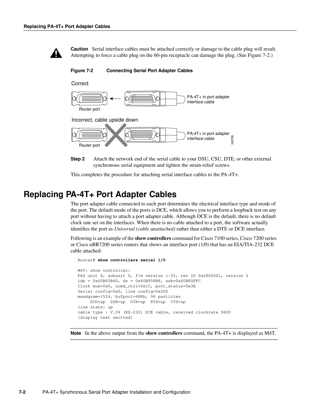
Caution Serial interface cables must be attached correctly or damage to the cable plug will result. Attempting to force a cable plug on the
Figure 7-2 Connecting Serial Port Adapter Cables
Correct
Router port
Incorrect, cable upside down
Router port
H9706
Step 2 Attach the network end of the serial cable to your DSU, CSU, DTE, or other external synchronous serial equipment and tighten the
This completes the procedure for attaching serial interface cables to the
Replacing PA-4T+ Port Adapter Cables
The port adapter cable connected to each port determines the electrical interface type and mode of the port. The default mode of the ports is DCE, which allows you to perform a loopback test on any port without having to attach a port adapter cable. Although DCE is the default, there is no default clock rate set on the interfaces. When there is no cable attached to a port, the software actually identifies the port as Universal (cable unattached) rather than either a DTE or DCE interface.
Following is an example of the show controllers command for Cisco 7100 series, Cisco 7200 series or Cisco uBR7200 series routers that shows an interface port (1/0) that has an
Router# show controllers serial 1/0
M4T: show controller:
PAS unit 8, subunit 0, f/w version
Clock mux=0x0, ucmd_ctrl=0x1C, port_status=0x3E Serial config=0x0, line config=0x200 maxdgram=1524, bufpool=48Kb, 96 particles
DCD=up DSR=up DTR=up RTS=up CTS=up line state: up
cable type : V.24
Note In the above output from the show controllers command, the
