Identifying Port Adapter Slot and
VIP2 Ports
In the router, physical port addresses specify the actual physical location of each interface port on the router interface processor end. (See Figure
Note Although the processor slots in the
•
•
The first number identifies the interface processor slot in which the VIP2 is installed.
The second number identifies the port adapter slot on the VIP2, and is either 0 or 1.
•The third number identifies the interface ports on each
Interface ports on a
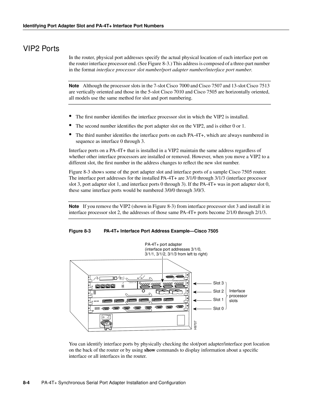
Figure 8-3 shows some of the port adapter slot and interface ports of a sample Cisco 7505 router. The interface port addresses for the installed PA-4T+ are 3/1/0 through 3/1/3 (interface processor slot 3, port adapter slot 1, and interface ports 0 through 3). If the PA-4T+ was in port adapter slot 0, these same interface ports would be numbered 3/0/0 through 3/0/3.
Note If you remove the VIP2 (shown in Figure
Figure 8-3 PA-4T+ Interface Port Address Example—Cisco 7505
(interface port addresses 3/1/0, 3/1/1, 3/1/2, 3/1/3 from left to right)
|
|
|
| EJECT | SLOT | 1 |
| |
NORMAL |
|
|
|
|
| 0 | ||
|
|
|
|
| SLOT |
| ||
0 | 1 | 2 | 3 |
| LINK |
|
| |
|
|
| 1 | 3 |
|
| ||
|
|
|
|
| 0 | 2 |
|
|
ETHERNET 10BT
CPU | HALT | RESET |
|
|
|
|
|
|
|
|
|
|
|
|
| ||
TD | TD | TC | RD | RC LB CD | TD | TC | RD | RC LB CD |
|
ROUTE SWITCH PROCESSOR
![]()
![]()
![]()
![]()
![]()
![]() CONSOLE
CONSOLE ![]() FAST SERIAL, ENHANCED
FAST SERIAL, ENHANCED
TD | TC | RD | RC LB CD | TD | TC | RD | RC LB CD |
|
| Slot 3 | Interface |
|
| ||
|
| Slot 2 | |
|
| ||
|
| Slot 1 | processor |
|
| slots | |
|
| ||
|
| Slot 0 |
|
|
|
| |
H9707 |
| ||
You can identify interface ports by physically checking the slot/port adapter/interface port location on the back of the router or by using show commands to display information about a specific interface or all interfaces in the router.