Cables and Pinouts
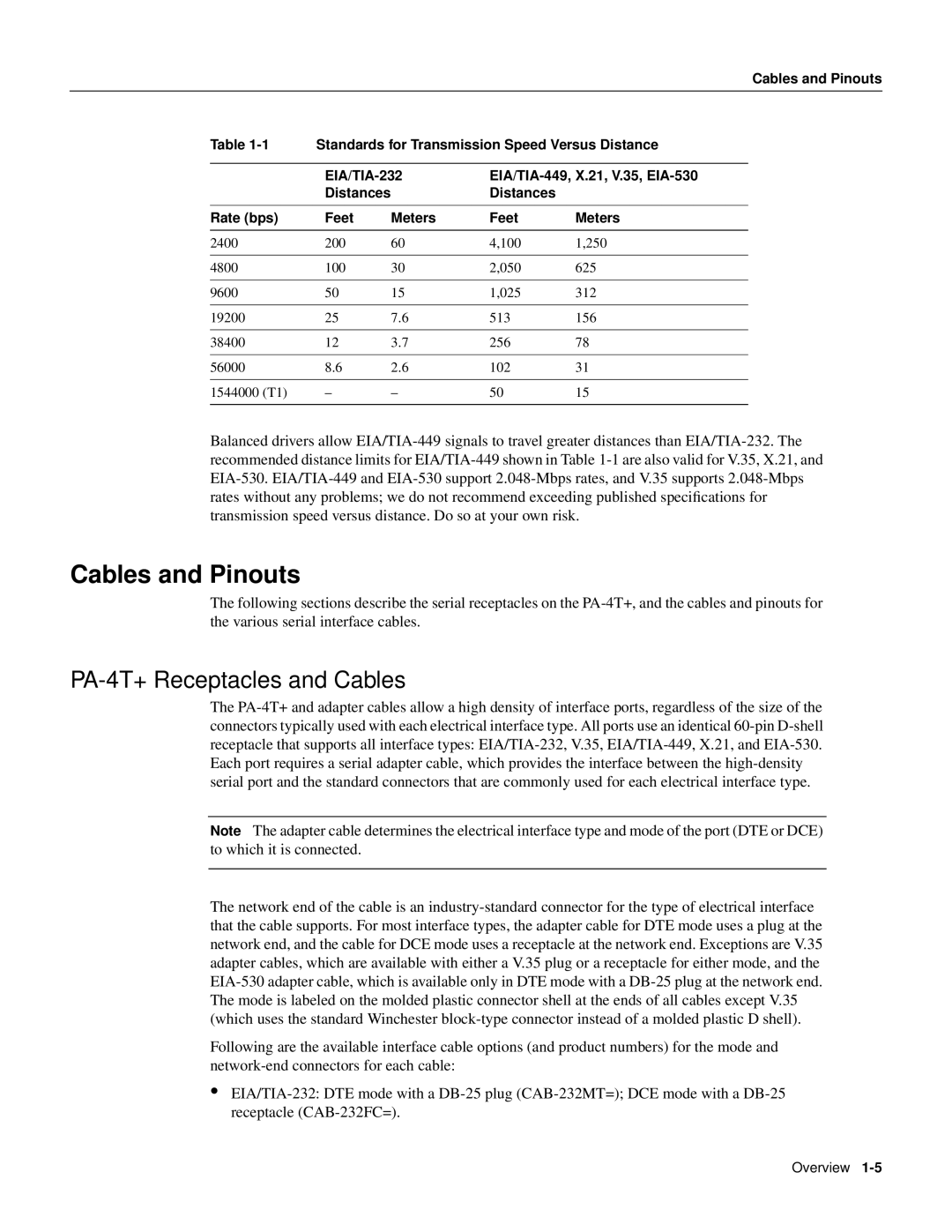
Table 1-1 | Standards for Transmission Speed Versus Distance |
| | |
| EIA/TIA-232 | EIA/TIA-449, X.21, V.35, EIA-530 |
| Distances | | Distances | |
| | | | |
Rate (bps) | Feet | Meters | Feet | Meters |
| | | | |
2400 | 200 | 60 | 4,100 | 1,250 |
| | | | |
4800 | 100 | 30 | 2,050 | 625 |
| | | | |
9600 | 50 | 15 | 1,025 | 312 |
| | | | |
19200 | 25 | 7.6 | 513 | 156 |
| | | | |
38400 | 12 | 3.7 | 256 | 78 |
| | | | |
56000 | 8.6 | 2.6 | 102 | 31 |
| | | | |
1544000 (T1) | – | – | 50 | 15 |
| | | | |
Balanced drivers allow EIA/TIA-449 signals to travel greater distances than EIA/TIA-232. The recommended distance limits for EIA/TIA-449 shown in Table 1-1 are also valid for V.35, X.21, and EIA-530. EIA/TIA-449 and EIA-530 support 2.048-Mbps rates, and V.35 supports 2.048-Mbps rates without any problems; we do not recommend exceeding published specifications for transmission speed versus distance. Do so at your own risk.
Cables and Pinouts
The following sections describe the serial receptacles on the PA-4T+, and the cables and pinouts for the various serial interface cables.
PA-4T+ Receptacles and Cables
The PA-4T+ and adapter cables allow a high density of interface ports, regardless of the size of the connectors typically used with each electrical interface type. All ports use an identical 60-pin D-shell receptacle that supports all interface types: EIA/TIA-232, V.35, EIA/TIA-449, X.21, and EIA-530. Each port requires a serial adapter cable, which provides the interface between the high-density serial port and the standard connectors that are commonly used for each electrical interface type.
Note The adapter cable determines the electrical interface type and mode of the port (DTE or DCE) to which it is connected.
The network end of the cable is an industry-standard connector for the type of electrical interface that the cable supports. For most interface types, the adapter cable for DTE mode uses a plug at the network end, and the cable for DCE mode uses a receptacle at the network end. Exceptions are V.35 adapter cables, which are available with either a V.35 plug or a receptacle for either mode, and the EIA-530 adapter cable, which is available only in DTE mode with a DB-25 plug at the network end. The mode is labeled on the molded plastic connector shell at the ends of all cables except V.35 (which uses the standard Winchester block-type connector instead of a molded plastic D shell).
Following are the available interface cable options (and product numbers) for the mode and network-end connectors for each cable:
•EIA/TIA-232: DTE mode with a DB-25 plug (CAB-232MT=); DCE mode with a DB-25 receptacle (CAB-232FC=).