LEDs
Table | X.21 Adapter Cable Signals |
|
|
|
|
|
| ||||
|
|
|
|
|
|
| |||||
DTE Cable |
|
| DCE Cable |
|
|
| |||||
|
|
|
|
|
|
|
|
|
|
| |
Router End, HD1 |
|
|
| Network End, | Router End, HD |
|
|
|
| Network End, | |
|
|
|
|
|
|
| |||||
|
|
|
|
|
|
|
|
|
|
|
|
Signal |
| Pin |
| Pin | Signal | Signal | Pin |
|
| Pin | Signal |
|
|
|
|
|
|
|
|
|
|
|
|
Shield ground |
| 46 |
| 1 | Shield ground | Shield ground | 46 |
|
| 1 | Shield ground |
|
|
|
|
|
|
|
|
|
|
| |
TxD/RxD+ |
| 11 | 2 | Transmit+ | RxD/TxD+ | 11 | 2 | Transmit+ | |||
|
|
|
|
|
|
|
|
|
|
|
|
TxD/RxD– |
| 12 | 9 | Transmit– | RxD/TxD– | 12 |
| 9 | Transmit– | ||
|
|
|
|
|
|
|
|
|
|
| |
RTS/CTS+ |
| 9 | 3 | Control+ | CTS/RTS+ | 9 | 3 | Control+ | |||
|
|
|
|
|
|
|
|
|
|
|
|
RTS/CTS – |
| 10 | 10 | Control– | CTS/RTS – | 10 |
| 10 | Control– | ||
|
|
|
|
|
|
|
|
|
|
| |
RxD/TxD+ |
| 28 | <— | 4 | Receive+ | TxD/RxD+ | 28 | <— | 4 | Receive+ | |
|
|
|
|
|
|
|
|
|
|
|
|
RxD/TxD– |
| 27 | <— | 11 | Receive– | TxD/RxD– | 27 |
| <— | 11 | Receive– |
|
|
|
|
|
|
|
|
|
|
| |
CTS/RTS+ |
| 1 | <— | 5 | Indication+ | RTS/CTS+ | 1 | <— | 5 | Indication+ | |
|
|
|
|
|
|
|
|
|
|
|
|
CTS/RTS – |
| 2 | <— | 12 | Indication– | RTS/CTS– | 2 |
| <— | 12 | Indication– |
|
|
|
|
|
|
|
|
|
|
| |
RxC/TxCE+ |
| 26 | <— | 6 | Timing+ | TxC/RxC+ | 26 | <— | 6 | Timing+ | |
|
|
|
|
|
|
|
|
|
|
|
|
RxC/TxCE– |
| 25 | <— | 13 | Timing– | TxC/RxC – | 25 |
| <— | 13 | Timing– |
|
|
|
|
|
|
|
|
|
|
|
|
Circuit ground |
| 15 |
| 8 | Circuit ground | Circuit ground | 15 |
|
| 8 | Circuit ground |
|
|
|
|
|
|
|
|
|
|
|
|
Ground |
| 48 |
|
| Shorting group | Ground | 48 |
|
|
| Shorting |
Mode_2 |
| 47 |
|
|
| Mode_2 | 47 |
|
|
| group |
|
|
|
|
|
|
|
|
|
|
|
|
Ground |
| 51 |
|
| Shorting group | Ground | 51 |
|
|
|
|
Mode_DCE |
| 52 |
|
|
| Mode_DCE | 52 |
|
|
|
|
|
|
|
|
|
|
|
|
|
|
|
|
1 HD = high density.
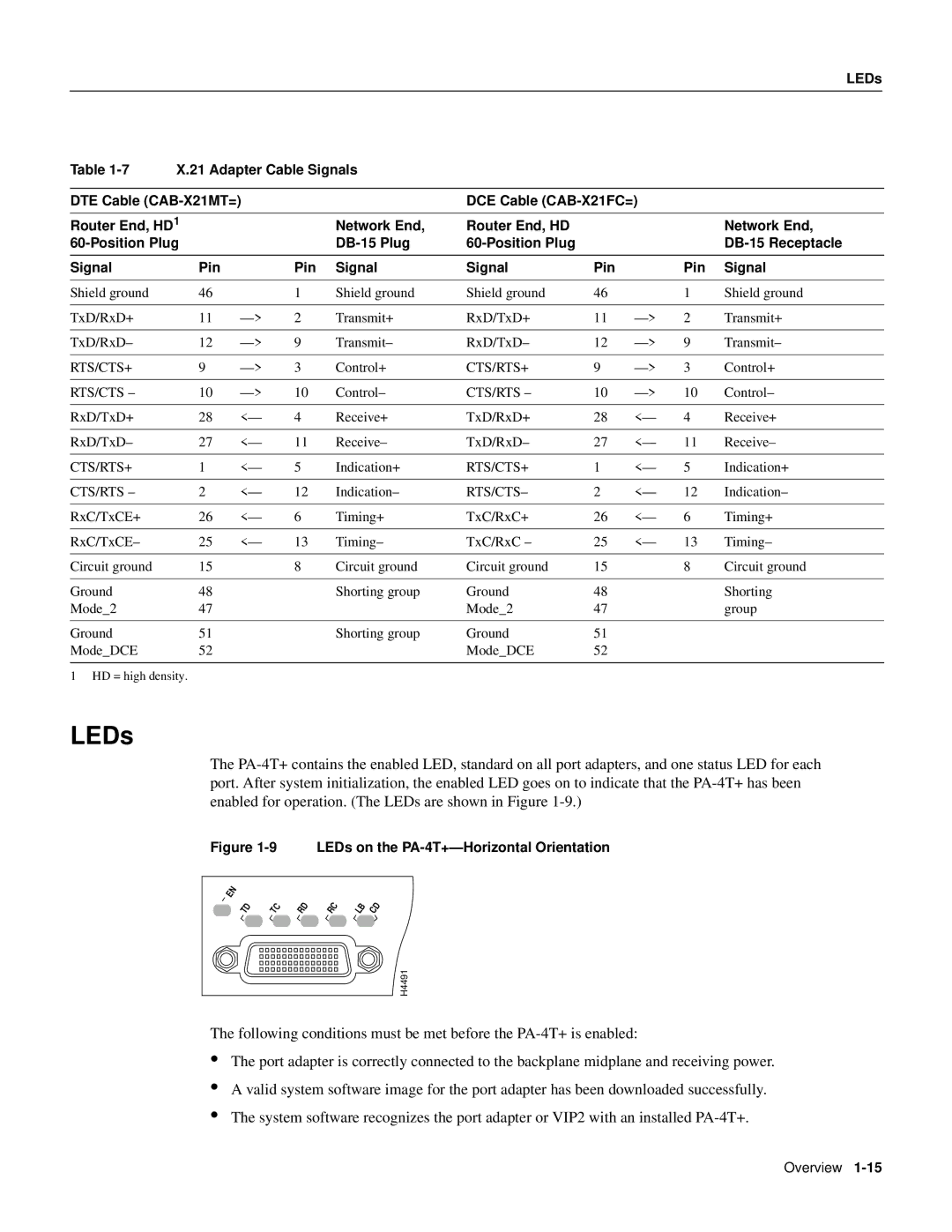
LEDs
The
Figure 1-9 LEDs on the PA-4T+—Horizontal Orientation
EN
TD | TC | RD | RC | LB | CD |
H4491
The following conditions must be met before the
•
•
•
The port adapter is correctly connected to the backplane midplane and receiving power.
A valid system software image for the port adapter has been downloaded successfully.
The system software recognizes the port adapter or VIP2 with an installed
Overview