Installation Overview
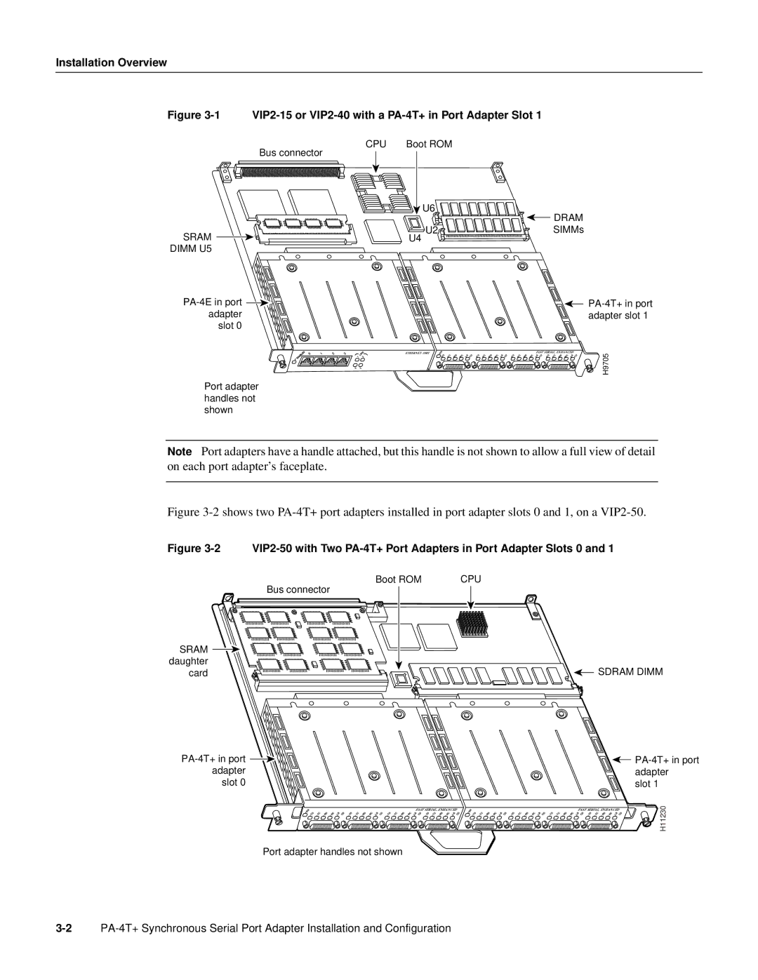
Figure 3-1 VIP2-15 or VIP2-40 with a PA-4T+ in Port Adapter Slot 1
CPU | Boot ROM |
|
Bus connector |
|
|
| U6 | DRAM |
|
| |
SRAM | U2 | SIMMs |
U4 |
| |
DIMM U5 |
|
|
| ||
adapter |
| adapter slot 1 |
slot 0 |
|
|
0 | 1 | 2 | 3 |
Port adapter handles not shown
1 | LINK |
3 | |
0 | 2 |
EN |
|
|
|
| CD |
|
|
|
|
|
|
|
|
|
| FAST SERIAL, ENHANCED | CD | ||||
TD | TC | RD | RC | LB | TD | TC | RD | RC | LB | CD | TD | TC | RD | RC | LB CD | TD | TC | RD | RC LB | ||
H9705
Note Port adapters have a handle attached, but this handle is not shown to allow a full view of detail on each port adapter’s faceplate.
Figure 3-2 shows two PA-4T+ port adapters installed in port adapter slots 0 and 1, on a VIP2-50.
Figure 3-2 VIP2-50 with Two PA-4T+ Port Adapters in Port Adapter Slots 0 and 1
Boot ROM | CPU |
Bus connector |
|
SRAM |
|
daughter | SDRAM DIMM |
card |
adapter | adapter |
slot 0 | slot 1 |
EN |
|
|
|
|
|
|
|
|
|
|
|
|
|
|
|
| FAST SERIAL, ENHANCED |
| |||||
TD | TC | RD | RC | LB | CD | TD | TC | RD | RC | LB | CD | TD | TC | RD | RC | LB CD | TD | TC | RD | RC LB | CD | ||
| |||||||||||||||||||||||
EN |
|
|
|
|
|
|
|
|
|
|
|
|
|
|
|
| FAST SERIAL, ENHANCED |
| |||||
TD | TC | RD | RC | LB | CD | TD | TC | RD | RC | LB | CD | TD | TC | RD | RC | LB CD | TD | TC | RD | RC LB | CD | ||
| |||||||||||||||||||||||
![]() H11230
H11230
Port adapter handles not shown