MC-519
Configuring Headend Broadband Access Router Features
MC-520
Headend Overview
Topology of a Typical Broadband Network
Voice over IP Services
MC-523
Telco Return
TOD
MC-524
MC-525
QoS Features
Service Class Profiles
Multiple Service IDs
MC-526
TAG/NetFlow Switching
QoS Profile Enforcement
MC-527
Tag Switching
Netflow Switching
Committed Access Rate CAR
Security Features
Weighted Random Early Detection
Weighted Fair Queueing
MC-529
Cable Modem and Multicast Authentication Using Radius
Docsis Baseline Privacy
Upstream Address Verification
MC-530
Traffic Shaping Features
Operations and Provisioning Features
Dynamic Ranging
CPE Limitation
Downstream Channel ID Configuration
Burst Profile Configuration
Downstream Frequency Override
Spectrum Management
MC-533
Headend Broadband Access Router Configuration Prerequisites
MC-534
Headend Broadband Access Router Configuration Tasks
Activating the Downstream Carrier
Configuring the Downstream Cable Interface
CMTS01# configure terminal
CMTS01config# interface cable 6/0
MC-536
Setting the Downstream Center Frequency
Troubleshooting Tips
Verifying the Downstream Carrier
MC-537
CMTS01config-if#cable downstream frequency
Verifying the Downstream Center Frequency
MC-538
Setting the Downstream Channel ID
Setting the Downstream Mpeg Framing Format Annex B
Verifying the Downstream Channel ID
MC-539
Setting the Downstream Modulation
Verifying the Downstream Mpeg Framing Format
Verifying the Downstream Modulation
MC-540
Setting the Downstream Interleave Depth
CMTS01config-if#cable downstream interleave-depth
Verifying the Downstream Interleave Depth
MC-541
Setting the Downstream Helper Address
Verifying the Downstream Helper Address
MC-542
Setting Downstream Rate Limiting
MC-543
Configuring the Upstream Cable Interface
Verifying Downstream Rate Limiting
MC-544
Setting the Upstream Frequency
CMTS01# show controllers cable 6/0 u0
Verifying the Upstream Frequency
MC-545
Channel-width width
Setting the Upstream Channel Width
Verifying Upstream Channel Width
MC-546
MC-547
Setting the Upstream Input Power Level
MC-548
Verifying the Upstream Input Power Level
Activating Upstream Admission Control
Verifying Upstream Admission Control
MC-549
Activating Upstream FEC
MC-550
Router# more systemrunning-config
Specifying Upstream Minislot Size
Verifying Upstream FEC
MC-551
Activating the Upstream Scrambler
Verifying Upstream Minislot Size
MC-552
CMTS01config-if#cable upstream usport scrambler
CMTS01# more systemrunning-config
Verifying the Upstream Scrambler
MC-553
Activating Upstream Differential Encoding
Activating Upstream Rate Limiting
Verifying Upstream Differential Encoding
MC-554
CMTS01config-if#no cable upstream usport rate-limit
Verifying Upstream Rate Limiting
MC-555
Activating Upstream Frequency Adjustment
Frequency-adjust averaging percentage
MC-556
Activating Upstream Power Adjustment
Verifying Upstream Frequency Adjustment
Continue seconds
Activating Upstream Timing Adjustment
Verifying Upstream Power Adjustment
MC-557
MC-558
Verifying Upstream Timing Adjustment
Activating the Upstream Ports
MC-559
Setting Upstream Backoff Values
Verifying the Upstream Ports
Data-backoff automatic
CMTS01config-if#cable upstream usport range
MC-560
Data-backoff start end
MC-561
Configuring and Activating Baseline Privacy
Verifying Upstream Data Backoff Automatic
MC-562
Configuring KEK Privacy
CMTS01config-if#cable privacy kek grace-time
MC-563
Configuring TEK Privacy
Verifying KEK Privacy
Verifying TEK Privacy
MC-564
Configuring and Activating Frequency Agility
Activating Baseline Privacy
Verifying Baseline Privacy
MC-565
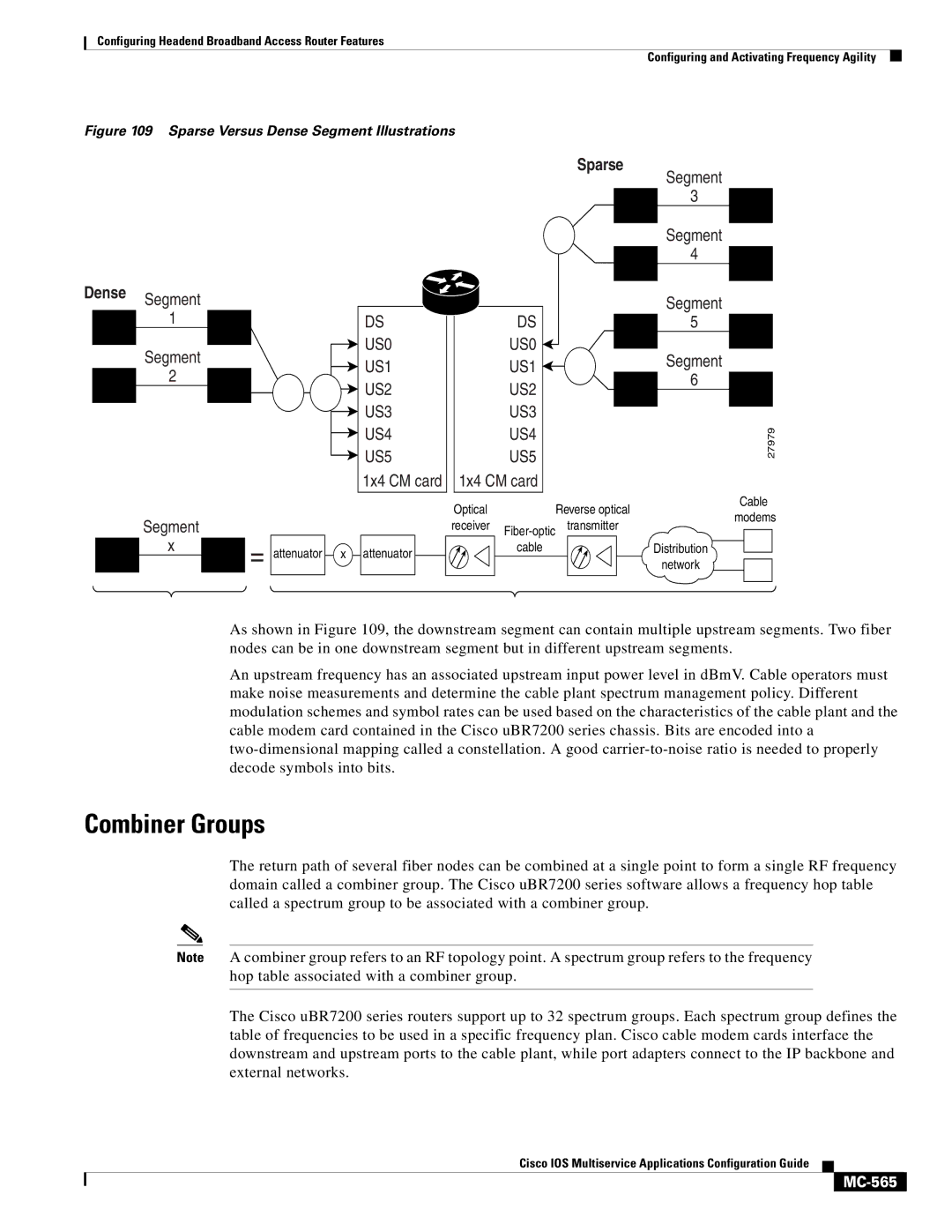
Combiner Groups
MC-566
Frequency Management Policy
MC-567
Determining the Upstream Ports Assigned to a Combiner Group
MC-568
Configuring and Activating Spectrum Groups
Creating Spectrum Groups
Verifying Spectrum Groups
MC-569
Command Purpose
MC-570
MC-571
Verifying Spectrum Group Configuration
Verifying Frequency Hopping
MC-572
Configuring Spectrum Group Characteristics
Threshold percent
Verifying Spectrum Group Characteristics
CMTS01config# cable spectrum-group groupnum hop
MC-573
Verifying Spectrum Group and Upstream Port Assignments
Activating IP Address Resolution Protocol
Assigning the Spectrum Group and the Upstream Ports
Activating Cable ARP Requests
MC-575
Activating Host-to-Host Communication Proxy ARP
Verifying ARP Requests
Verifying Cable Proxy ARP Requests
Configuring Dhcp Options
Activating Cable Proxy ARP Requests
Activating Cable Relay Agent
MC-577
Activating Dhcp giaddr
Verifying Dhcp giaddr Activation
Verifying ToD Service
Setting Service Options
Setting Optional IP Parameters
Configuring ToD Service
MC-579
Activating IP Multicast Echo
Activating IP Broadcast Echo
Verifying IP Multicast Echo
MC-580
Configuring Cable Profiles
Configuring Cable Modulation Profiles
Verifying IP Broadcast Echo
MC-581
Number profile
MC-582
Configuring QoS Profiles
Verifying Cable Modulation Profiles
MC-583
Verifying QoS Profiles
MC-584
Setting QoS Permission
Enforcing a QoS Profile Assignment
Verifying QoS Permission
MC-585
Managing Cable Modems on the HFC Network
Verifying a QoS Profile Assignment
Verifying Sync Message Interval
Configuring Sync Message Interval
Configuring Telco Return
Activating Cable Modem Authentication
MC-587
Verifying Cable Modem Authentication
Activating Cable Modem Upstream Address Verification
MC-588
CMTS01config-if#cable source-verify dhcp
Activating Cable Modem Insertion Interval
Verifying Cable Modem Upstream Address Verification
MC-589
CMTS01config-if#cable insertion-interval automatic
Verifying Cable Modem Insertion Interval
MC-590
Configuring Cable Modem Registration Timeout
Verifying the Maximum Number of Hosts
MC-591
Clearing and Resetting Cable Modems
Verifying Registration Timeout
MC-592
Verifying Cable Modem Clearing and Resetting
Clearing Cable Modem Counters
MC-593
Using Ping Docsis
Verifying that Cable Modem Counters are Cleared
Verifying Ping Docsis
MC-594
Spectrum Management Configuration Example
MC-595
Virtual Private Network Configuration Example
MC-596
MC-597
Ip http server Ip http authentication local No cdp run
MC-598
VoIP Configuration Example
Ip subnet-zero No ip domain-lookup
MC-599
MC-600
Telco Return Configuration Example
MC-601
Cable telco-return enable
Cable Reg
QoS Profile Enforcement Configuration Example
Cable Modem all reset
MC-602
MC-603
Troubleshooting Using Cable Flap Lists
Setting Cable Flap List Aging
CMTS01config# cable flap-list aging days
Verifying Cable Flap List Insertion Time
Setting Cable Flap List Insertion Time
Setting Cable Flap List Power Adjustment Threshold
Verifying Cable Flap List Aging
Verifying Cable Flap List Miss Threshold
Setting Cable Flap List Miss Threshold
Verifying Cable Flap List Power Adjustment Threshold
CMTS01config# cable flap-list miss-threshold misses
MC-606
Setting Cable Flap List Size
Clearing Cable Flap List
Verifying Cable Flap List Size