Configuring Headend Broadband Access Router Features
Configuring and Activating Frequency Agility
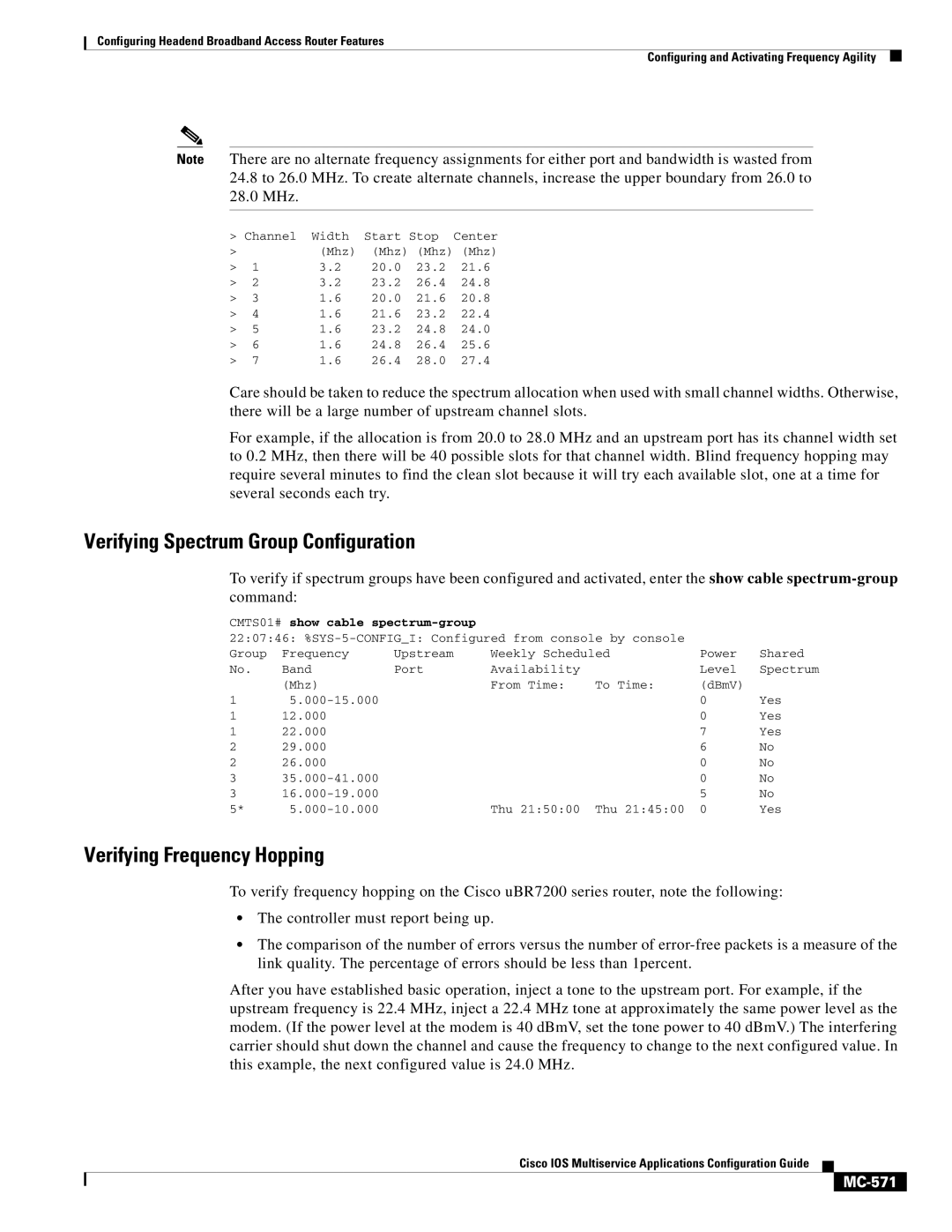
Note There are no alternate frequency assignments for either port and bandwidth is wasted from
24.8to 26.0 MHz. To create alternate channels, increase the upper boundary from 26.0 to
28.0MHz.
> Channel Width Start Stop Center
>(Mhz) (Mhz) (Mhz) (Mhz)
> | 1 | 3.2 | 20.0 | 23.2 | 21.6 |
> | 2 | 3.2 | 23.2 | 26.4 | 24.8 |
> | 3 | 1.6 | 20.0 | 21.6 | 20.8 |
> | 4 | 1.6 | 21.6 | 23.2 | 22.4 |
> | 5 | 1.6 | 23.2 | 24.8 | 24.0 |
> | 6 | 1.6 | 24.8 | 26.4 | 25.6 |
> | 7 | 1.6 | 26.4 | 28.0 | 27.4 |
Care should be taken to reduce the spectrum allocation when used with small channel widths. Otherwise, there will be a large number of upstream channel slots.
For example, if the allocation is from 20.0 to 28.0 MHz and an upstream port has its channel width set to 0.2 MHz, then there will be 40 possible slots for that channel width. Blind frequency hopping may require several minutes to find the clean slot because it will try each available slot, one at a time for several seconds each try.
Verifying Spectrum Group Configuration
To verify if spectrum groups have been configured and activated, enter the show cable
CMTS01# show cable |
|
|
|
| ||
22:07:46: |
|
| ||||
Group | Frequency | Upstream | Weekly Scheduled | Power | Shared | |
No. | Band | Port | Availability |
| Level | Spectrum |
| (Mhz) |
| From Time: | To Time: | (dBmV) |
|
1 |
|
|
| 0 | Yes | |
1 | 12.000 |
|
|
| 0 | Yes |
1 | 22.000 |
|
|
| 7 | Yes |
2 | 29.000 |
|
|
| 6 | No |
2 | 26.000 |
|
|
| 0 | No |
3 |
|
|
| 0 | No | |
3 |
|
|
| 5 | No | |
5* |
| Thu 21:50:00 | Thu 21:45:00 | 0 | Yes | |
Verifying Frequency Hopping
To verify frequency hopping on the Cisco uBR7200 series router, note the following:
•The controller must report being up.
•The comparison of the number of errors versus the number of
After you have established basic operation, inject a tone to the upstream port. For example, if the upstream frequency is 22.4 MHz, inject a 22.4 MHz tone at approximately the same power level as the modem. (If the power level at the modem is 40 dBmV, set the tone power to 40 dBmV.) The interfering carrier should shut down the channel and cause the frequency to change to the next configured value. In this example, the next configured value is 24.0 MHz.
Cisco IOS Multiservice Applications Configuration Guide