RAID Array 3000 Controller Shelf
12.After the UPS has been set to the correct input voltage level, set the UPS
13.This completes the Controller and Device Expansion Shelf cabling proce- dure. Dress and
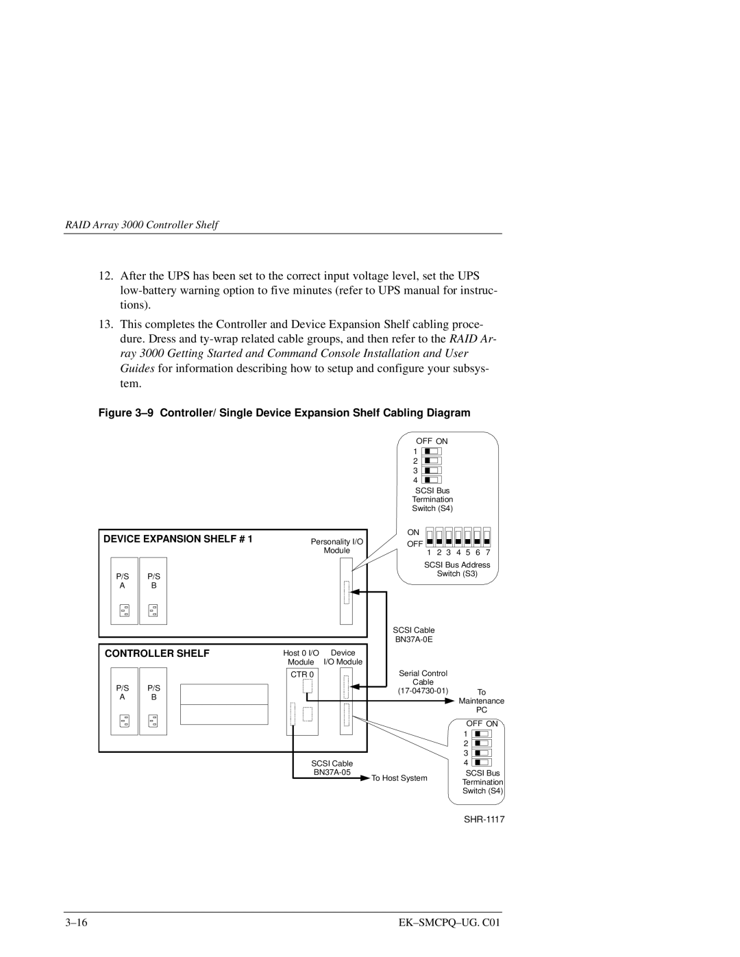
Figure 3–9 Controller/ Single Device Expansion Shelf Cabling Diagram
OFF ON 1 ![]()
![]() 2
2 ![]()
![]() 3
3 ![]()
![]() 4
4 ![]()
![]()
SCSI Bus
Termination Switch (S4)
DEVICE EXPANSION SHELF # 1
ON
Personality I/OOFF
Module
1 2 3 4 5 6 7
P/S | P/S |
A | B |
|
|
CONTROLLER SHELF
P/S | P/S |
A | B |
|
|
SCSI Bus Address
Switch (S3)
SCSI Cable
Host 0 I/O | Device |
|
|
|
|
|
| ||||
| Module | I/O Module |
|
|
|
|
|
| |||
|
|
|
|
|
| Serial Control |
|
|
|
|
|
| CTR 0 |
|
|
|
|
|
|
|
|
| |
|
|
|
|
|
| Cable |
|
|
|
|
|
|
|
|
|
|
|
|
| To | |||
|
|
|
|
|
|
| Maintenance | ||||
|
|
|
|
|
|
|
|
| PC | ||
|
|
|
|
|
|
| OFF ON | ||||
|
|
|
|
|
|
| 1 |
|
|
|
|
|
|
|
|
|
|
|
|
|
|
| |
|
|
|
|
|
|
|
|
|
|
| |
|
|
|
|
|
|
| 2 |
|
|
|
|
|
|
|
|
|
|
| 3 |
|
|
|
|
| SCSI Cable |
| 4 |
|
|
|
| ||||
| To Host System | SCSI Bus | |||||||||
|
|
|
|
|
| Termination | |||||
|
|
|
|
|
|
| |||||
Switch (S4)