Chapter 3. Installation and Maintenance
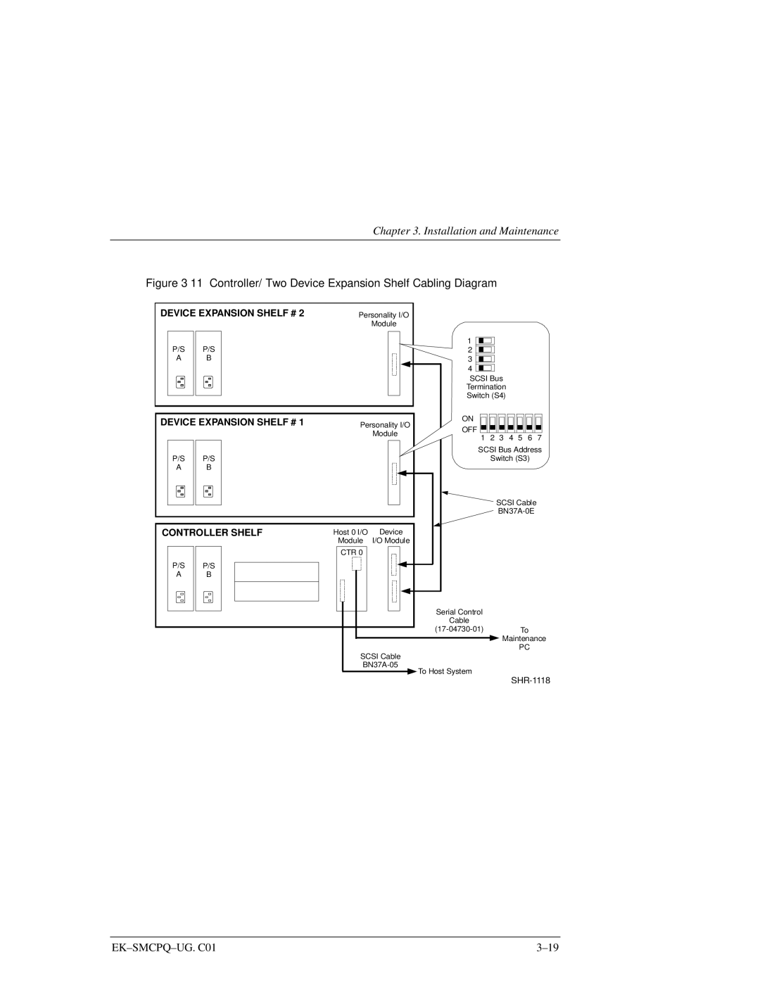
Figure 3–11 Controller/ Two Device Expansion Shelf Cabling Diagram
DEVICE EXPANSION SHELF # 2
P/S | P/S |
A | B |
|
|
DEVICE EXPANSION SHELF # 1
P/S | P/S |
A | B |
|
|
CONTROLLER SHELF
P/S | P/S |
A | B |
|
|
Personality I/O
Module
1 ![]()
![]()
![]()
![]() 2
2 ![]()
![]()
![]()
![]() 3
3 ![]()
![]()
![]()
![]() 4
4 ![]()
![]()
![]()
SCSI Bus Termination Switch (S4)
ON
Personality I/O
ModuleOFF ![]()
1 2 3 4 5 6 7
SCSI Bus Address
Switch (S3)
SCSI Cable
Host 0 I/O | Device | ||||
| Module | I/O Module | |||
|
|
|
|
|
|
| CTR 0 |
|
|
| |
Serial Control
Cable
![]() Maintenance
Maintenance
PC
SCSI Cable
![]() To Host System
To Host System
