Models CHS-810, CHS-814, CHS-819, and CHS-824
CHS Tangential Feed Granulators
Date Manual Number UGG011/0504 Serial Numbers Model Numbers
Technical Specification
Table of Contents
4. Safety Instructions
Installation
Spare Parts List
Service
Wiring Diagram
i i l Ta b l e o f C o n t e n t s
A. Customer Service
11. Accessories, Overview
10. Layout
12. Transport and Storage
i v l Ta b l e o f C o n t e n t s
P u r p o s e o f t h e U s e r G u i d e . . . . . . . . . . . . . 1
I n t r o d u c t i o n
H o w t h e G u i d e i s O r g a n i z e d . . . . . . . . . . . . 1
AT T E N T I O N
Purpose of the User Guide
How the Guide is Organized
Your Responsibility as a User
AT T E N T I O N Read This so no One Gets Hurt
WARNING Voltage hazard
1 I n t r o d u c t i o n
This manual applies to the CHS series of Conair granulators
Technical Specifications
Technical Specifications
Technical Specifications l 2
2 - 2 l Technical Specifications
Hardened cutter housing
Performance characteristics
SPECIFICATION NOTES
G e n e r a l
Function Description
S a f e t y S y s t e m
Function Description
General
Function Description
models with a conveyor, the hopper is equipped with a conveyor belt. The conveyor can be equipped with a metal detector
Safety System
Safety Switch
Emergency Stop
Before Starting
Star Knob
3 - 6 l Function Description
Safety Instructions
4 S a f e t y I n s t r u c t i o n s
S a f e t y I n s t r u c t i o n s l 4
Electrical installation must only be done by a competent electrician
Safety Instructions
During maintenance, pull out the plug on the distribution box
If the rotor must be turned manually - do this with great care
DANGER! High voltage
DANGER! Cutting or pinch risk
DANGER! Be careful
4 - 4 l S a f e t y I n s t r u c t i o n s
I n s t a l l a t i o n l 5
I n s t a l l a t i o n
I n s t a l l a t i o n
Pre-Start Checks
Two Hours After First Start
The granulator should be connected by a competent electrician
Electrical Connection
Check the direction of rotation of the granulator motor
If any direction of rotation should be incorrect
Opening the hopper
Opening of Hopper, Screen Box and Granule Bin
Opening the screen box
screen box, switch both the main switch and
Closing the Screen Box, Granule Bin and Hopper
Close the screen box and install the granule bin
Close the hopper
There is a pinch risk during closing, be careful
5 - 6 l M a i n t e n a n c e
Maintenance
Operation and Daily Maintenance
Operation and Daily Maintenance l 6
S t a r t i n g a n d S t o p i n g
Operation and Daily Maintenance
Starting and Stopping
6 - 2 l Operation and Daily Maintenance
Daily Inspection
Inspection
Weekly Inspection
Monthly Inspection
Cleaning
Switch “Off” both the main switch and the switch on the granulator
6 - 4 l Operation and Daily Maintenance
Re-install after cleaning
Fault-Finding
6 - 6 l Operation and Daily Maintenance
The granulator does not start
Operation and Daily Maintenance l 6
6 - 8 l Operation and daily maintenance
S e r v i c e
Changing the knives
Service
Removing the knives
Changing the knives
Installing the Knives
First install the rear, fixed knife
Install the rotating knives
6 Install screws A with washers B, and tighten so that they hold
Then install the front, fixed knife
Sharpening Knives - Granulators with Open Cutter
Sharpening Knives
Grind the cutting angle of the knives to
V-Belts, Inspection, and Adjustment
Transmission
The granulator is driven by 3 V-belts Checking the V-belts
V-belt Adjustment
Transmission continued
Lubrication
Cutter Housing
7 - 1 0 l Service
Cutter Pulley/Motor Pulley
Installing
Removal
Cutter Pulley
7 - 1 2 l Service
S a f e t y
Spare Parts List
Ordering Spare Parts
Spare Parts List
Cutting Chamber
Art. no
Description
Art. no
Staggered Rotor
Description
8 - 4 l S p a r e P a r t s L i s t
List
Open Rotor
Spare
Parts
Knives, Open Cutter
Knives
8 - 6 l S p a r e P a r t s L i s t
Art. no
Screen
Screen Box
8 - 8 l S p a r e P a r t s L i s t
Granule Bin Manual Optional
8 - 1 0 l S p a r e P a r t s L i s t
Vaccum Suction /Blower F-7/F-15
Pos Qty
Art. no
Hopper
8 - 12 l S p a r e P a r t s L i s t
Hopper - Noise encapsulated machine with with Conveyor
S p a r e P a r t s L i s t l 8 - 1
Hopper Device
8 - 14 l S p a r e P a r t s L i s t
Sound Cabin
8.17 Enclosure/Body
8 - 1 6 l S p a r e P a r t s L i s t
Safety
9 Wiring Diagram
Wiring Diagram
W i r i n g D i a g r a m
W i r i n g D i a g r a m l 9
Wiring diagram
Relay functions and normal settings
Current Sensing Relay
Default setting for this granulator
Connection
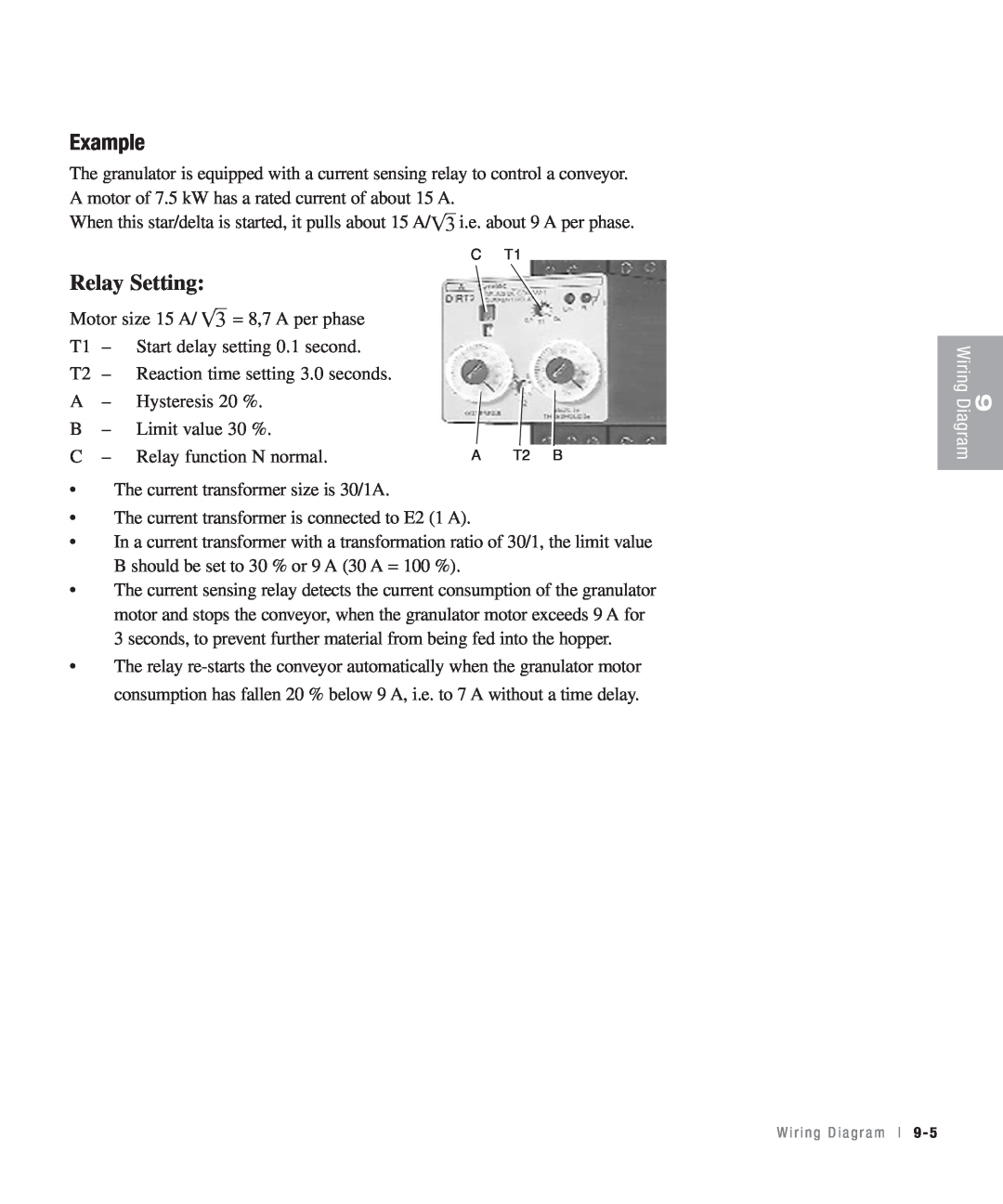
Relay Setting
Example
9 - 6 l W i r i n g D i a g r a m
1 0 Layout
L a y o u t
1 0 - 2 l L a y o u t
Layout
1650mm64.96in
1490mm58.66in
27.56in.700mm
1790mm70.47in
1 0 - 4 l L a y o u t
1 1 Accessories
A c c e s s o r i e s
Ordering Spare Parts
A c c e s s o r i e s
Pre - Setting of Rotating Knives, Granulator with Open Cutter
Setting Up the Knives
Installation of Pre-Set Knives
Tighten the fastening screws, tightening torque 162.26lb-ft 220 Nm
Installation
Third Fixed Knife
Sharpening
Band Conveyor
Safety
Electrical Connection
The band conveyor should be connected up by an authorised electrician
Trouble-shooting
Maintenance
Starting
If the belt moves obliquely
11 - 8 l A c c e s s o r i e s
Spare Parts for the Band Conveyor
U n p a c k i n g a n d C h e c k i n g
Transport and Storage
Transport and
Storeage
Lifting and Transport to Place of Use
Transport and storage
Unpacking and Checking
Positioning in Place of Use
Long-Term Storage/Conservation
Storage
1 2 - 4 l T r a n s p o r t a n d S t o r a g e
We’re Here to Help
How to Contact Customer Ser vice
Before You Call
From outside the United States, call
Performance Warranty
Equipment Guarantee
Warranty Limitations
A - 2 l A p p e n d i